GIGABYTE B650 AORUS ELITE AX Motherboard Review |
您所在的位置:网站首页 › vga cpu boot dram › GIGABYTE B650 AORUS ELITE AX Motherboard Review |
GIGABYTE B650 AORUS ELITE AX Motherboard Review
|
GIGABYTE B650 AORUS ELITE AX Motherboard Review Summary
Verdict At the end of the day, the B650 AORUS ELITE AX is almost a balanced feature set provider motherboard that the user can get for their daily driver need. The game is strong with the storage department of this motherboard and USB Type-C Gen 2×2 port provisions as well, though don’t expect to find PCIe Gen 5 X16 slot. Pros Effective VRM Cooling 2 NVMe Gen 5 SSD Plethora of USB ports USB Type-C Gen 2 Quick Flash Plus EZ-Latch on PCIe Slot EZ-Latch on M.2 Ports Overall good performanceCons No X4 PCIe Slot No External Temperature Sensor Ports No Debug LED Official Site Check Price X670 Vs B650 Best B650 MotherboardsEarlier we took a look at the X670E AORUS MASTER motherboard from the GIGABYTE. In this content, we are taking a spin on the B650 AORUS ELITE AX motherboard which is aimed more towards the upper-budget segment while still boasting some good features but without breaking the bank. Let’s start with the salient features of the motherboard: AMD Socket AM5:Supports AMD Ryzen™ 7000 Series Processors Unparalleled Performance: Twin 14*+2+1 Phases Digital VRM Solution Dual Channel DDR5:4*SMD DIMMs with AMD EXPO™ & Intel® XMP Memory Module Support Next Generation Storage:1*PCIe 5.0 x4 and 2*PCIe 4.0 x4 M.2 Connectors Fully Covered Heatpipe & M.2 Thermal Guard: To Ensure VRM Power Stability & 25110 PCIe 5.0 M.2 SSD Performance EZ-Latch: PCIe x16 Slot & M.2 Connectors with Quick Release & Screwless Design Fast Networks:2.5GbE LAN & Wi-Fi 6E 802.11ax Extended Connectivity:DP, HDMI, Rear USB-C® 10Gb/s, Front USB-C® 20Gb/s Smart Fan 6:Features Multiple Temperature Sensors, Hybrid Fan Headers with FAN STOP Q-Flash Plus: Update BIOS Without Installing the CPU, Memory, and Graphics CardThe twin above means 7 parallel phases. 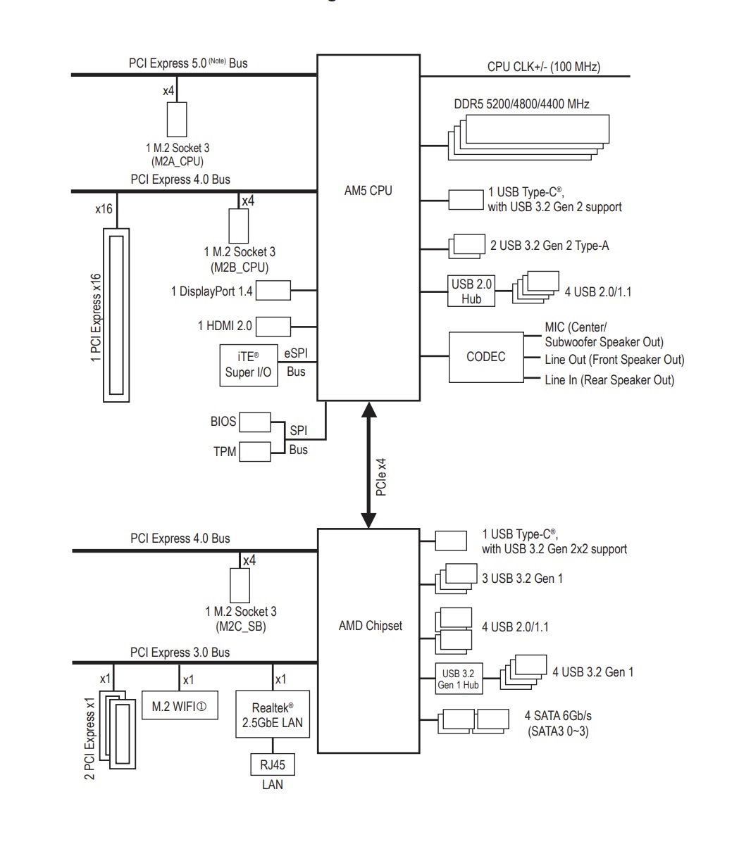 GIGABYTE B650 AORUS ELITE Layout GIGABYTE B650 AORUS ELITE Layout
The above picture shows the block diagram of the B650 AORUS ELITE AX motherboard. We can see that the CPU is providing native support for 1x PCIe x16 slot and 2x NVMe x4 ports but with a glaring difference. The M.2 port labeled as M2A_CPU is actually on Gen 5 bus whereas the PCIe x16 slot and M2B_CPU M.2 port are on the gen 4 bus. In simple words, this motherboard supports M.2 Gen 5 but there is no Gen 5-based PCIe slot. The DDR5 support of up to 5200MHz is mentioned. This is with the help of a BIOS update. Since the new 7000 series CPUs will have iGPU, there is an HDMI 2.0 and DisplayPort 1.4 connectivity options from the CPU. There is one USB Type-C Gen 2 port and two USB 3.2 Gen 2 Type-A ports along with a USB 2.0 hub which is driving up to 4x USB 2.0/1.1 ports. The chipset is connected to the CPU socket using PCIe x4 bridging. The third M.2 port labeled as M2C_SB is on the Gen 4 bus. GIGABYTE has provided 3x M.2 ports in total with 2 being driven by Gen 4 bus and one on the Gen 5 bus. This is good news for storage lovers on a budget. There are two more PCIe slots that are on the Gen 3 bus and rated for X1 speed each. The very reason for being X1 speed is that they share the same bus with LAN and wireless connectivity. This also means that they are not related to the 4x SATA ports. We have ample USB connectivity with up to 13 connections including the front panel USB 3.2 Gen2x2 Type-C port. Product: B650 AORUS ELITE AX Price: Price is TBD Specifications
Packaging and Unboxing Specifications
Packaging and Unboxing
 GIGABYTE B650 AORUS ELITE Box & Packing GIGABYTE B650 AORUS ELITE Box & Packing
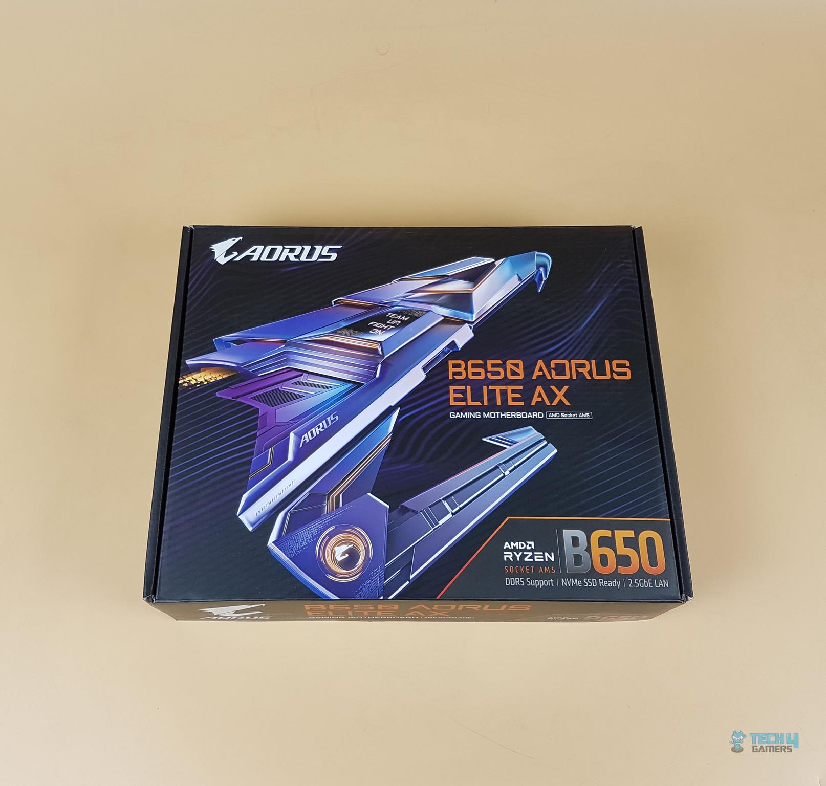
The motherboard is shipped inside a colorful box. The motherboard is PCIe 5.0 ready for the NVMe only. There is a colorful and stylish AORUS Falcon picture. 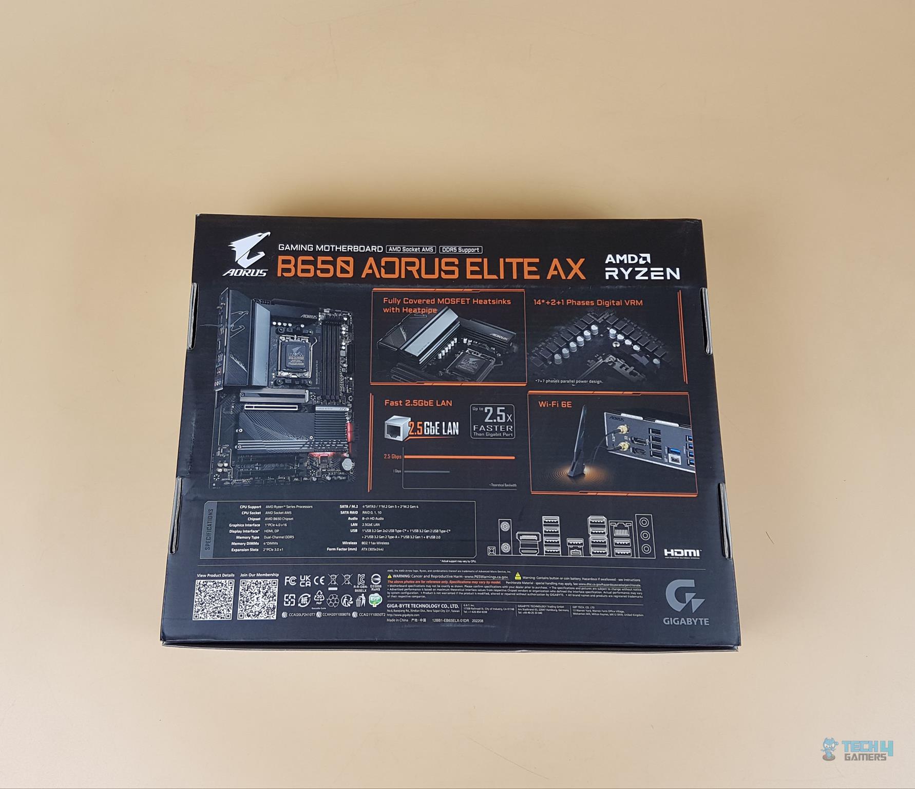 The backside of the box The backside of the box
The backside of the box has the following 4 features highlighted: Fully covered MOSFET Covers 5GbE LAN 14+2+1 Power Phases Ei-Fi 6E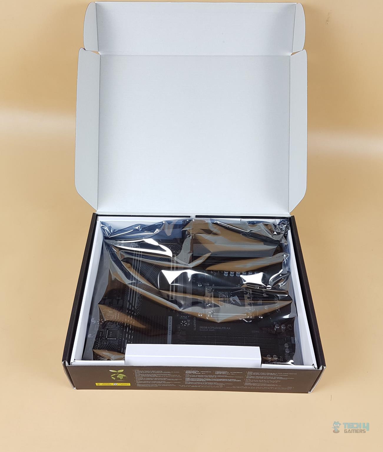 Opening the box Opening the box
Take a glimpse of the motherboard with the box wide open. ContentsThese include: 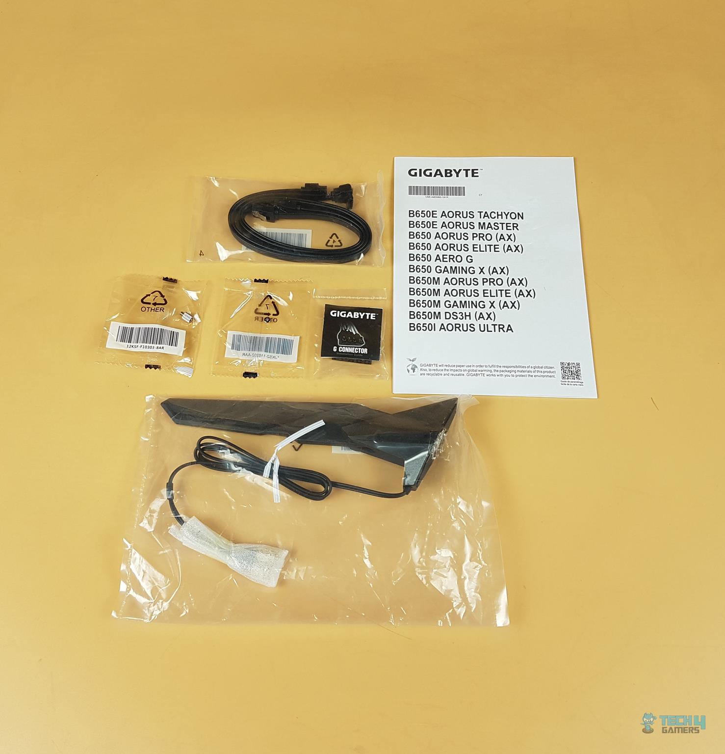 Contents inside the box
1x Motherboard
1x WiFi Antenna
2x SATA Cables
1x Front Panel G Connector
1x M.2 Standoff
1x M.2 Screw
1x Paper Leaflet Contents inside the box
1x Motherboard
1x WiFi Antenna
2x SATA Cables
1x Front Panel G Connector
1x M.2 Standoff
1x M.2 Screw
1x Paper Leaflet
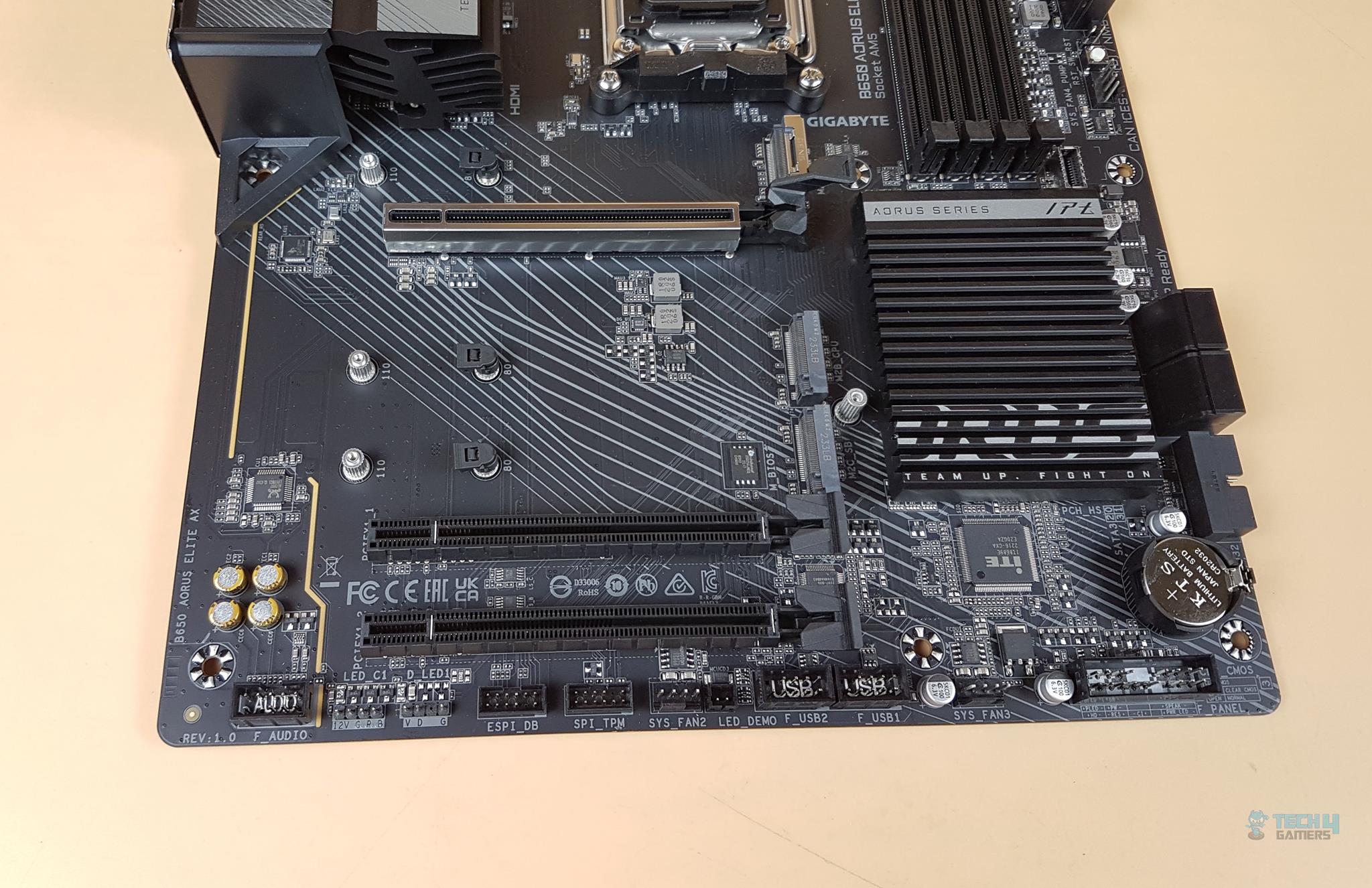
There is no user manual provided in the box. Closer LookThe B650 AORUS ELITE AX motherboard is a mid-range segment motherboard from the GIGABYTE. The motherboard has a standard ATX size and is still adequately feature-rich. GIGABYTE has retained the stenciling and design element from the previous generation however, at the same time, they have gone to another level in the design department of the motherboard to deliver a solid product for the enthusiasts. Let’s start exploring the motherboard.  Complete Layout Complete Layout
The above picture illustrates the overview of the motherboard layout and features. 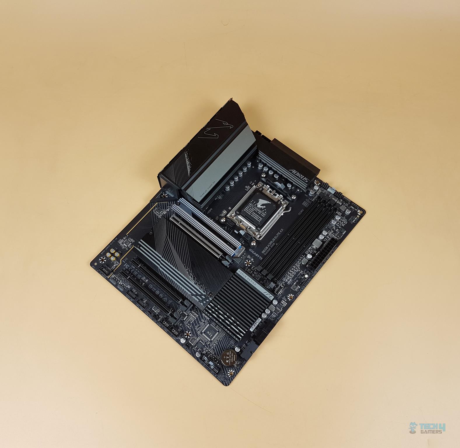 GIGABYTE B560 AORUS Elite AX Motherboard Front – Image Captured By Us. GIGABYTE B560 AORUS Elite AX Motherboard Front – Image Captured By Us.
Taking a glance at the motherboard, we have a black color PCB. The heatsinks have black and gray color tone. The Chipset cover has RGB elements. So, the RGB Fusion 2.0 is somewhat in play for the user on this motherboard because the lighting is not that elaborative. GIGABYTE has given due consideration to the cooling requirement of the key components all around. The chipset area is covered in tandem with the M.2 ports cover giving one stylish outlook. We have a new AM5 socket, 4x DIMM slots for DDR5 RAM, 3x PCIe slots at X16/X2/X2, 4x SATA ports, a plethora of USB ports, an on-board audio solution driven by Realtek ALC897, RealTek 2.5 GbE NIC, on-board WiFi 6E and nice handy I/O connectivity options. The 8-layered and 2x Copper PCB has a standard ATX form factor measuring 30.5cmX24.4cm and has support for Microsoft Windows 10 and 11. Let’s dive in. CPU Socket, Heatsink, VRM, and Power Delivery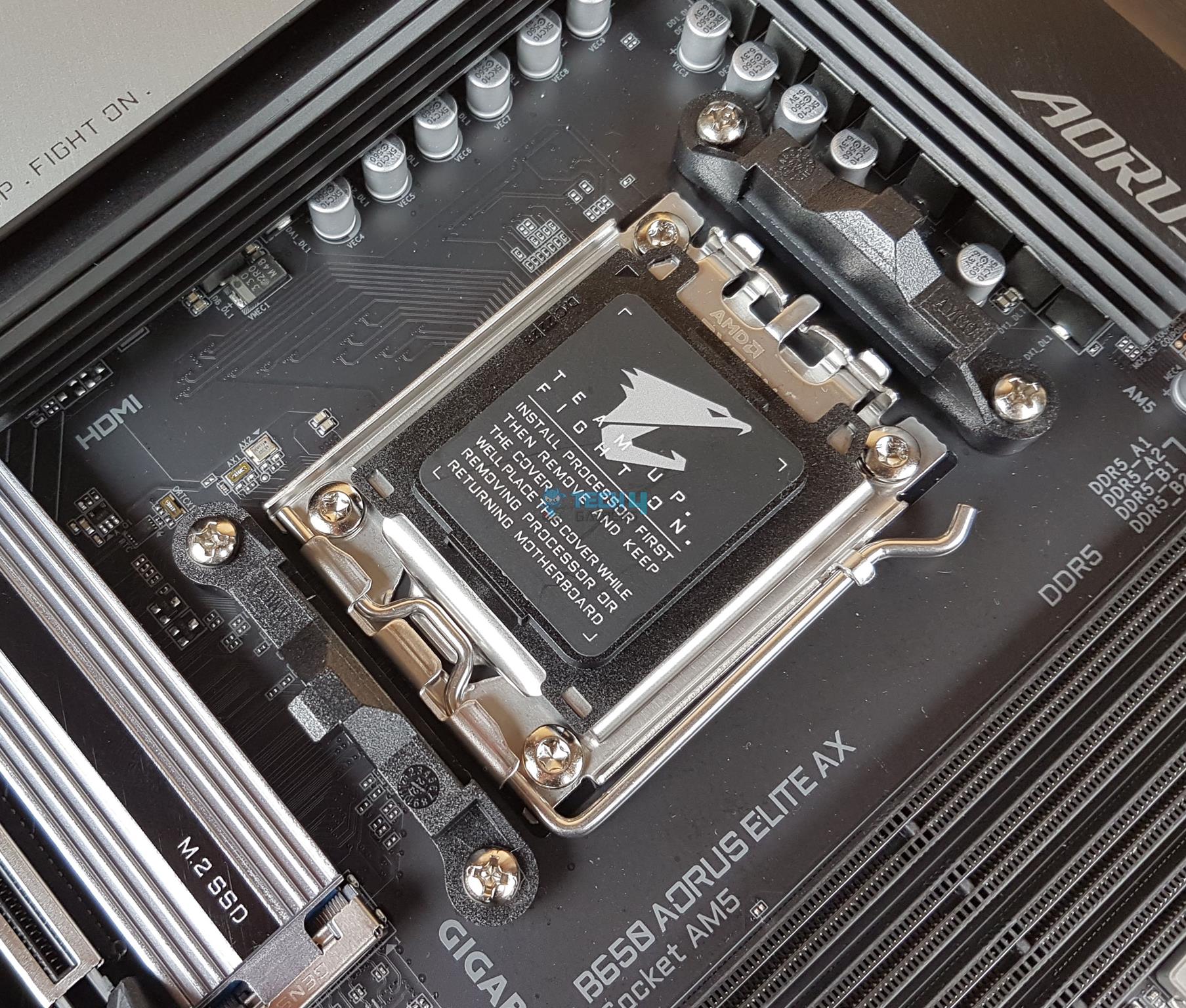 CPU Socket CPU Socket
The B650 AORUS ELITE AX motherboard features a new socket from AMD named AM5. It is named LGA 1718 as AMD has resorted to Land Grid Array (LGA). The previous generation of Ryzen series CPUs is not compatible with this socket. This is a flip-chip design supporting new 7000 series CPUs and DDR5 memory modules. There is a protective cover over the socket area. 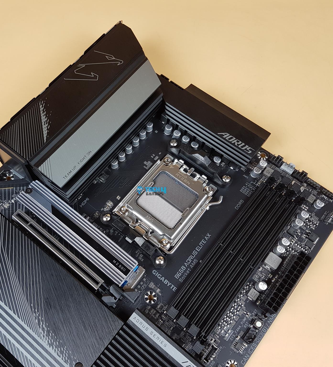 GIGABYTE B560 AORUS Elite AX Motherboard GIGABYTE B560 AORUS Elite AX Motherboard
The above picture shows the socket after removing the protective cover. The socket looks segmented into two. Take note of the brackets on the top and at the bottom of the socket. They are the same design as we have seen on the previous generation AM4 sockets. Since the socket size is the same, any cooler compatible with the socket AM4 (using stock AMD backplate or hook-style installation) can be installed on the AM5 as well. AMD in this way has provided a good solution for the customer as they would not need to upgrade or change the cooling solution for the new socket. The motherboard has support for an Integrated Graphics Processor as follow: 1 x DisplayPort, supporting a maximum resolution of 3840×2160@144 Hz, Support for DisplayPort 1.4 version and HDR. 1 x HDMI port, supporting a maximum resolution of 4096×2160@60 Hz, Support for HDMI 2.1 version and HDCP 2.3.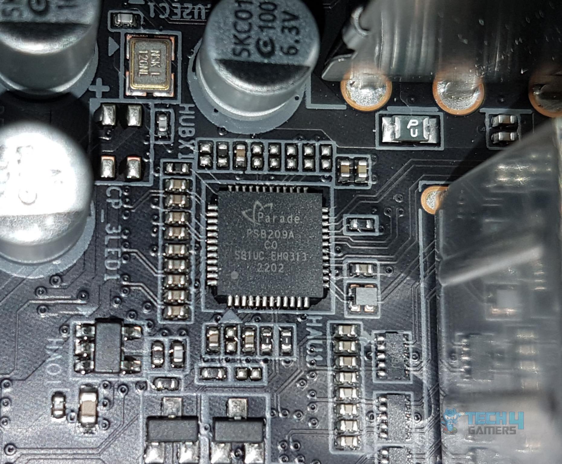 Integrated Graphics Card Integrated Graphics Card
The PS8209A is a low-power HDMI shifter and redriver which is compliant with HDMI 2.0 specifications up to 6.0Gbps.
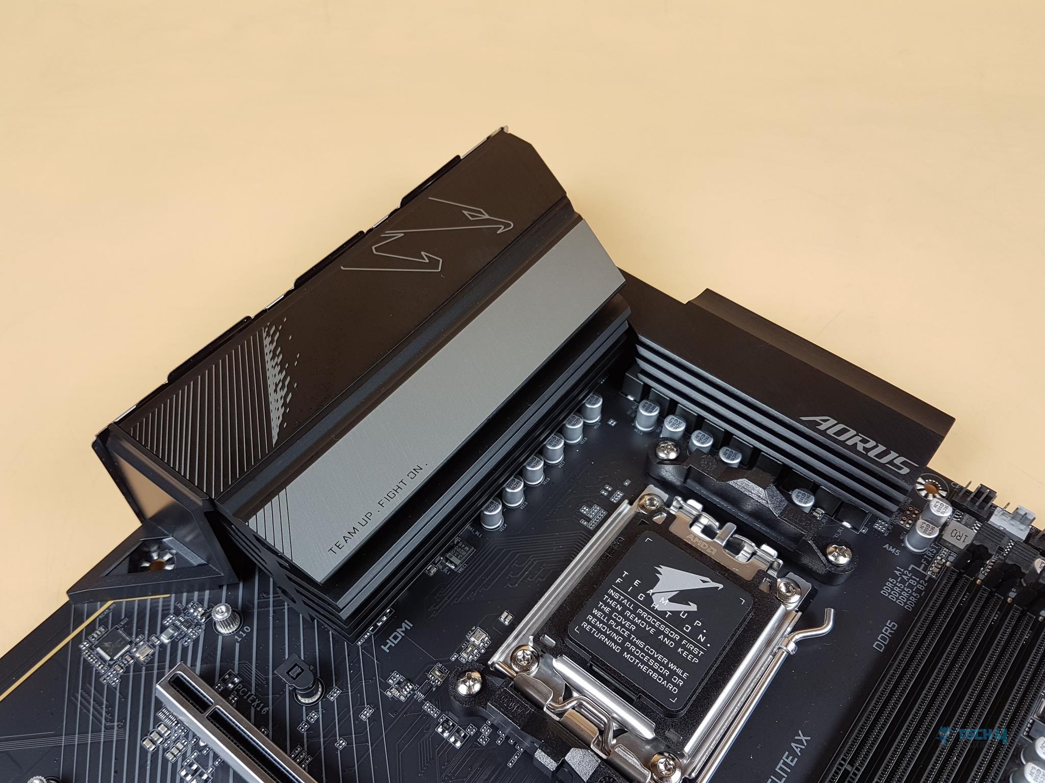
From a cooling perspective, GIGABYTE has implemented an effective solution. There is a massive heatsink underneath the I/O cover. TMOS is a single-piece heatsink. Its one-piece design and larger surface drastically improve the cooling performance against competitors’ multi-piece designs. TMOS features several channels and inlets on the heatsink. This design allows for the airflow to go through which leads to a great improvement of the heat transfer performance.
The above picture shows the I/O cover from a different angle. The elegant design speaks for itself. 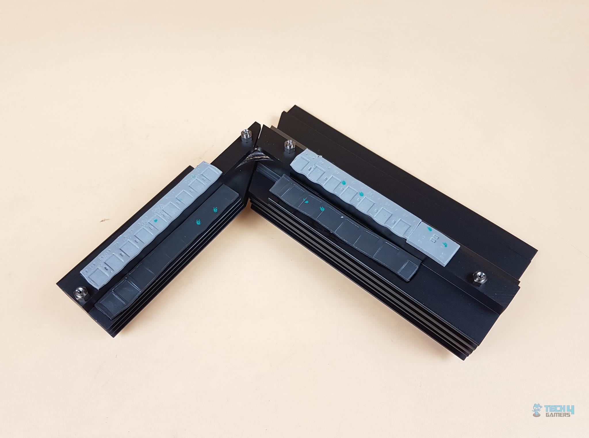 IO Plate IO Plate
The above picture shows the beefy cooling solution for the provided MOSFETs and VRM. 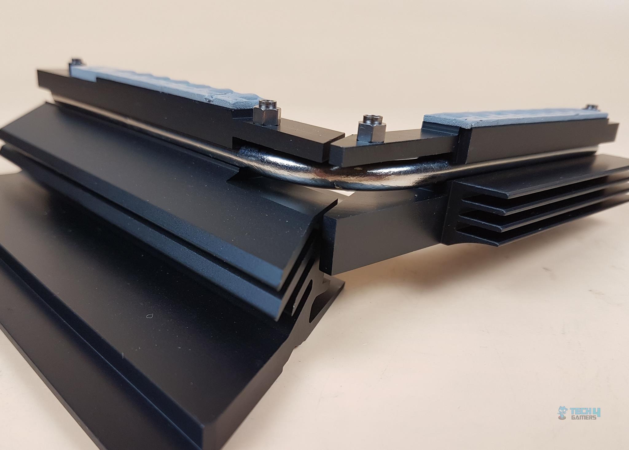 Cooling Heatsink Cooling Heatsink
Both heatsinks are connected using a 6mm thick copper heat pipe. The thermal pads are rated for up to 7W/mK. Since we are at it, let’s take a look at the power delivery of the motherboard. 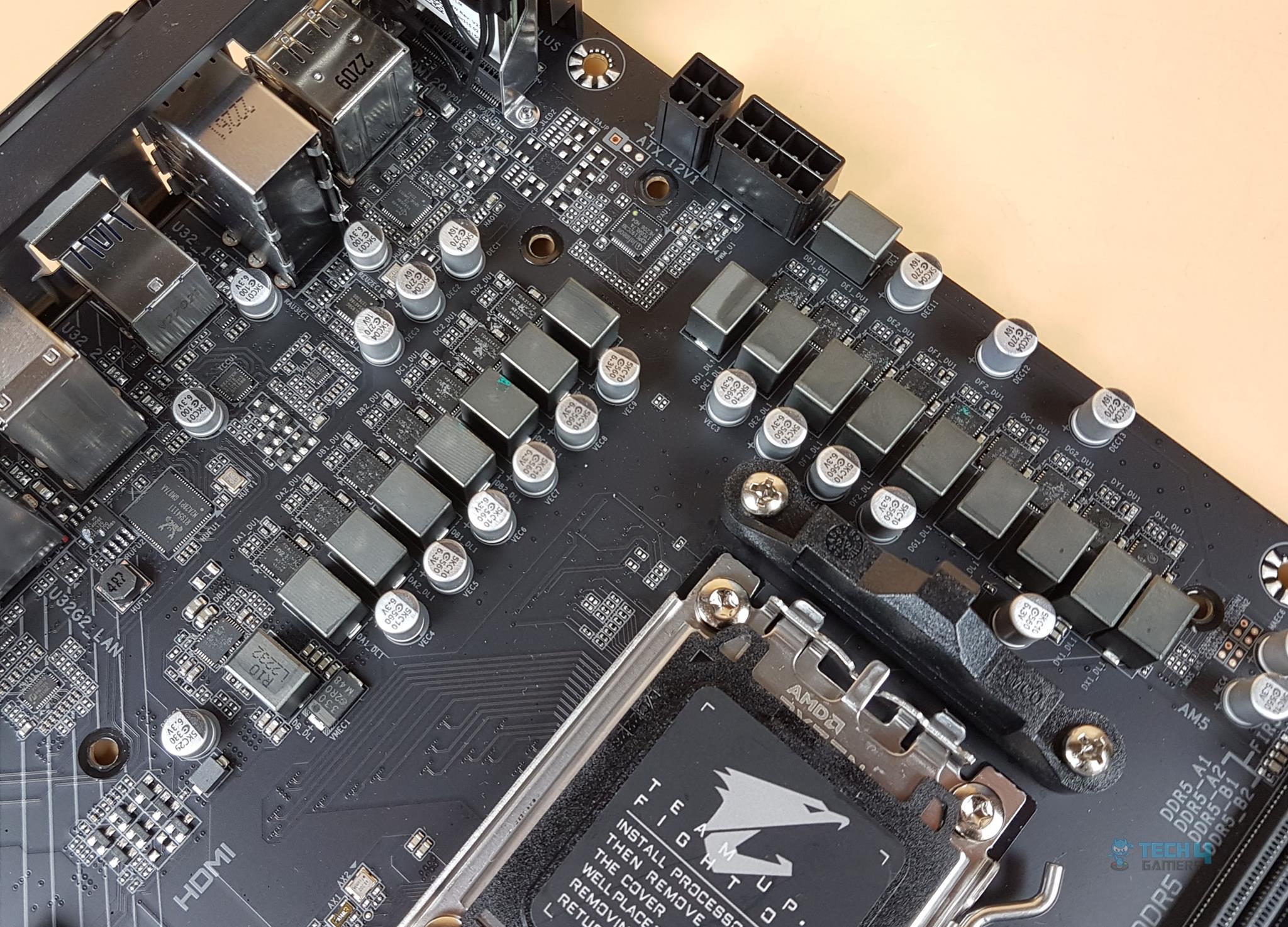 Power Capacitors Power Capacitors
The B650 AORUS ELITE AX motherboard has adequate digital power phases. There are 14 phases in parallel (not direct) for the VCore using Infineon TDA21472 SPS 70A making it 980A which is quite low compared to the 1680A on the X670E AORUS MASTER. Then there are 2x MOSFETs for SOC using ON NCP303160 SPS 60A with a total of 120A for SOC for stable power delivery to the iGPU. Lastly, we have 1x MOSFET for MISC using Renesas ISL99390 SPS 30A for stable power delivery to the PCIe lanes. In terms of power delivery, this motherboard seems adequate enough in this range though twin digital 14 phases sound like a doubler design to me. 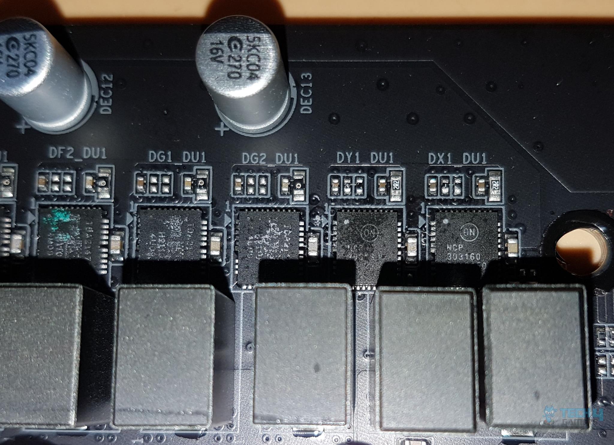 SOC Mofset SOC Mofset
The above picture shows the SOC MOSFET ON NCP303160. 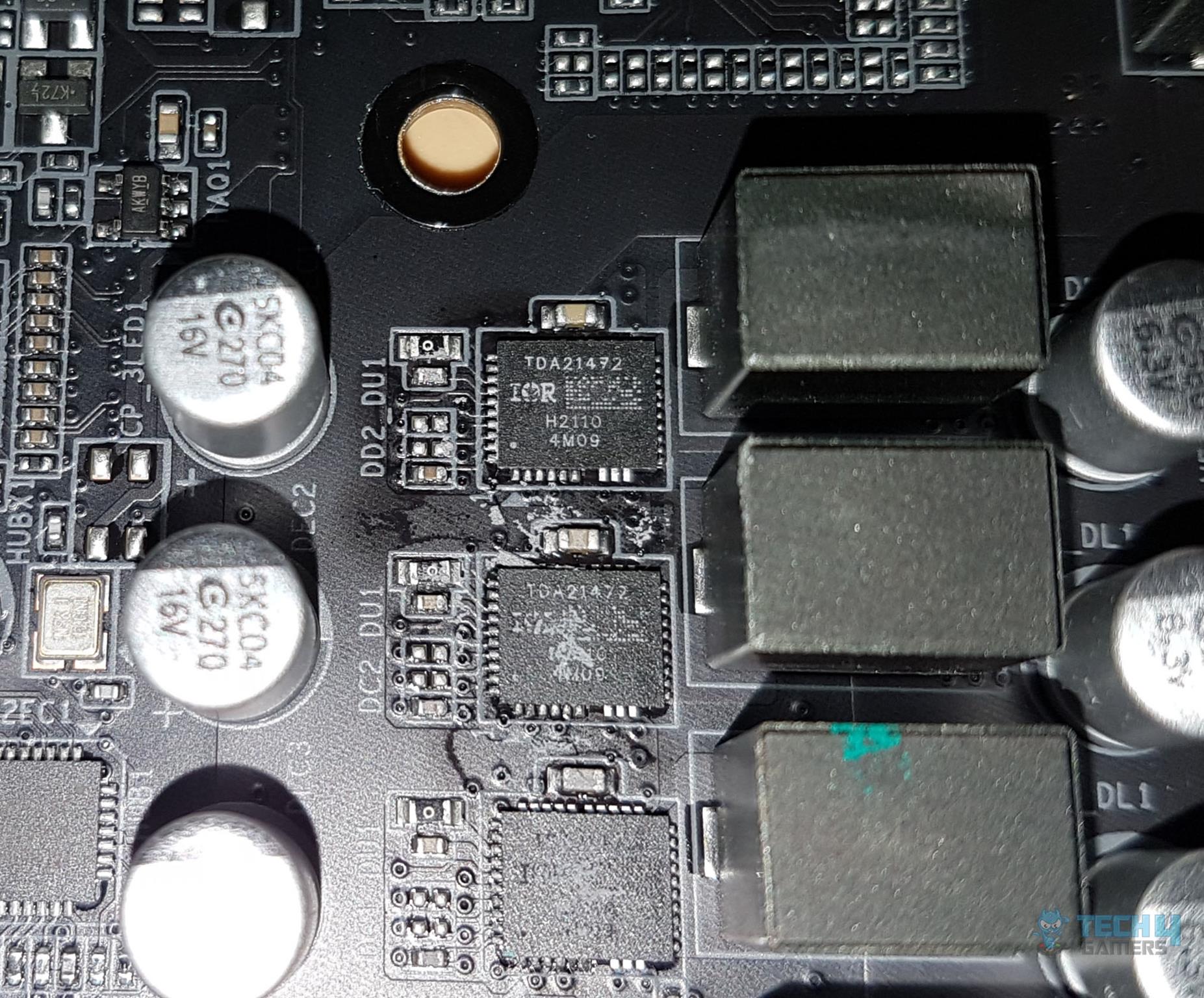 VCore Mofset VCore Mofset
The above picture shows the VCore MOSFET Infineon TDA21472. 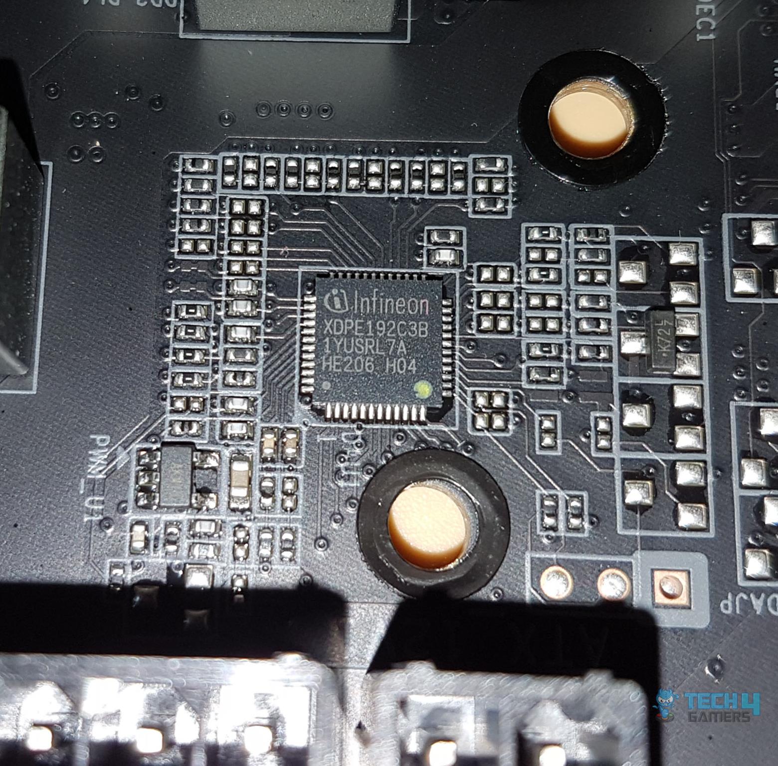 VRM Controller VRM Controller
GIGABYTE has employed Infineon VRM controller XDPE192C3B for integrated control of all three types of MOSFETs. 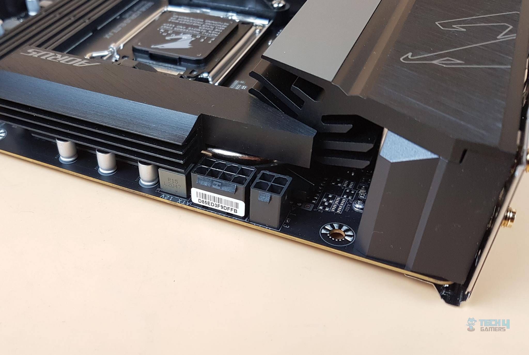 EPS Connector EPS Connector
The last piece of the puzzle for the CPU socket is the EPS connector. GIGABYTE has provided 1x 8-pin+1×4-pin EPS connectors to ensure a buttery smooth power supply. DIMM Slots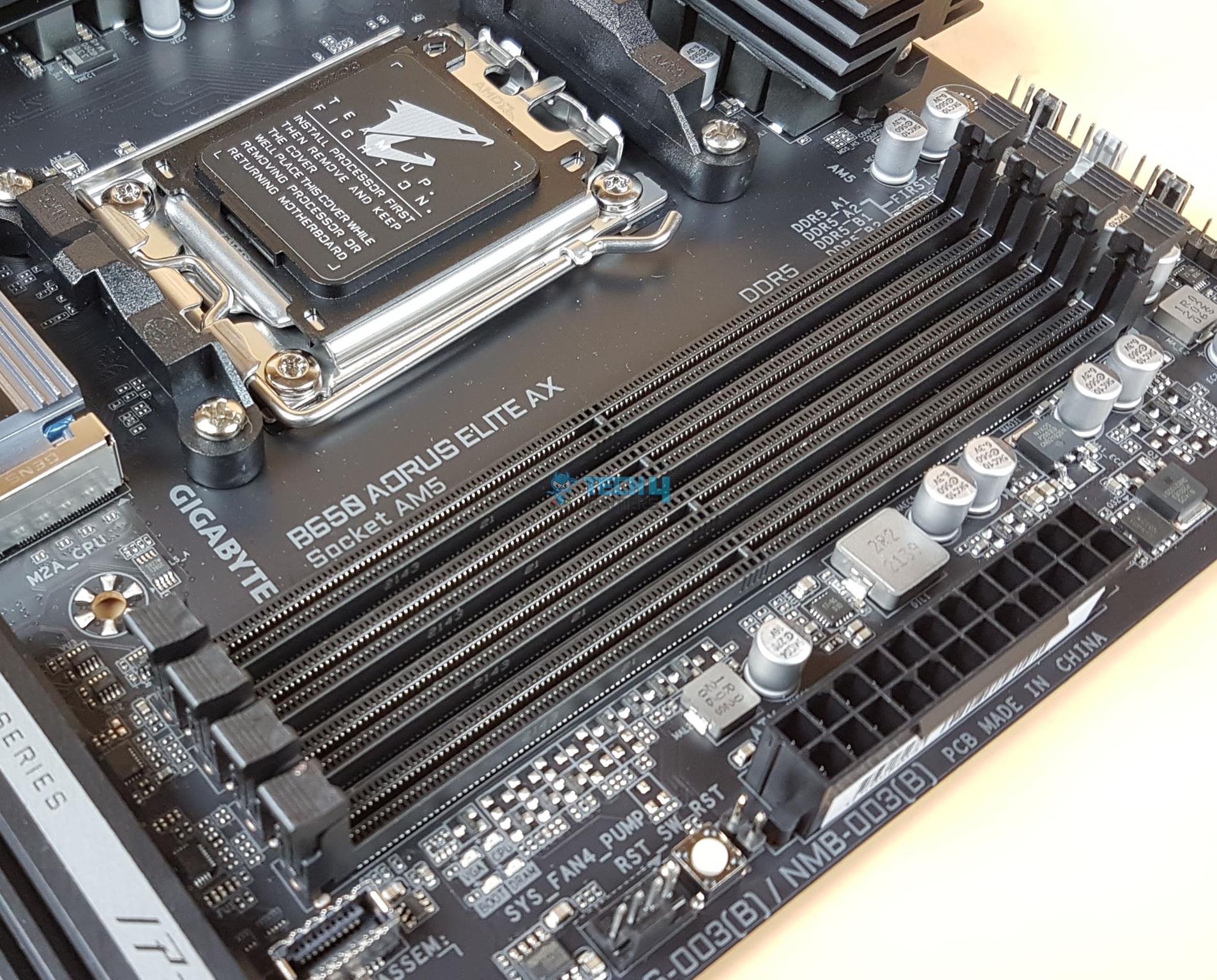 DDR5 RAM Slots DDR5 RAM Slots
The B650 AORUS ELITE AX motherboard has 4x DDR5-based DIMM slots which are not SMD stainless-steel reinforced. There is no anti-plate bending support. The DDR5 up to 6600MHz is supported (with BIOS update). By default, the board supports 4400, 4800, and 5200MHz. A total of up to 128GB RAM capacity is supported with a single stick density of 32GB. This is Dual Channel architecture and supports un-buffered DIMM 1Rx8/2Rx8/1Rx16 memory modules. 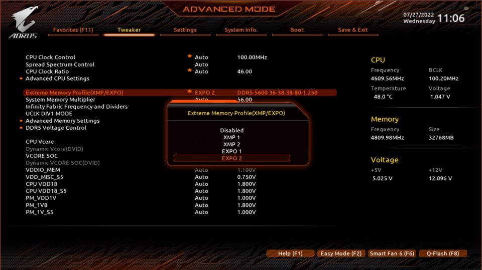 BIOS BIOS
This board supports AMD EXPO and Intel XMP profiles. EXPO stands for Extended Profiles for Overclocking. GIGABYTE AM5 MB supports both AMD EXPO and Intel XMP overclocking memory modules for maximal compatibility. MB will automatically detect both profiles format in SPD, users can choose to enable one of the profiles from the BIOS menu and easily reach overclocked memory performance. This board supports DDR5 Auto Booster to 5000MHz. This is a one-click operation that can be done in the UEFI/BIOS. The user can define and create their own SPD profile in Native, EXPO, and XMP 3.0 memory modules. One user-defined profile can be saved and loaded either locally or from/to an external storage device. This way the saved profile can be loaded on the other system and have that system configured in no time. The board also supports quick memory performance simulation based on user input clock and timing parameters. 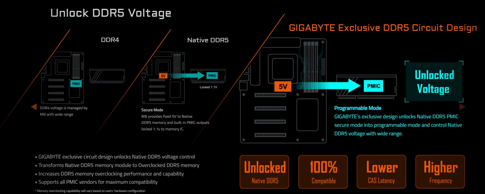 DDR5 Voltage DDR5 Voltage
By now, we know that some DDR5 modules come with locked PMIC (1.1V) whereas some high-end and high-performance kits come with unlocked PMIC. This is not necessarily a bad thing. The locked PMIC would hurt the overclocking of the kit only. One solution is to bypass the locking mechanism from the UEFI/BIOS and this is exactly what the X670E AORUS MASTER provides. The user can take the advantage of the function and unlock the natively locked PMIC into a programmable one and push the kits beyond boundaries with a wide range of overclocking possibilities. 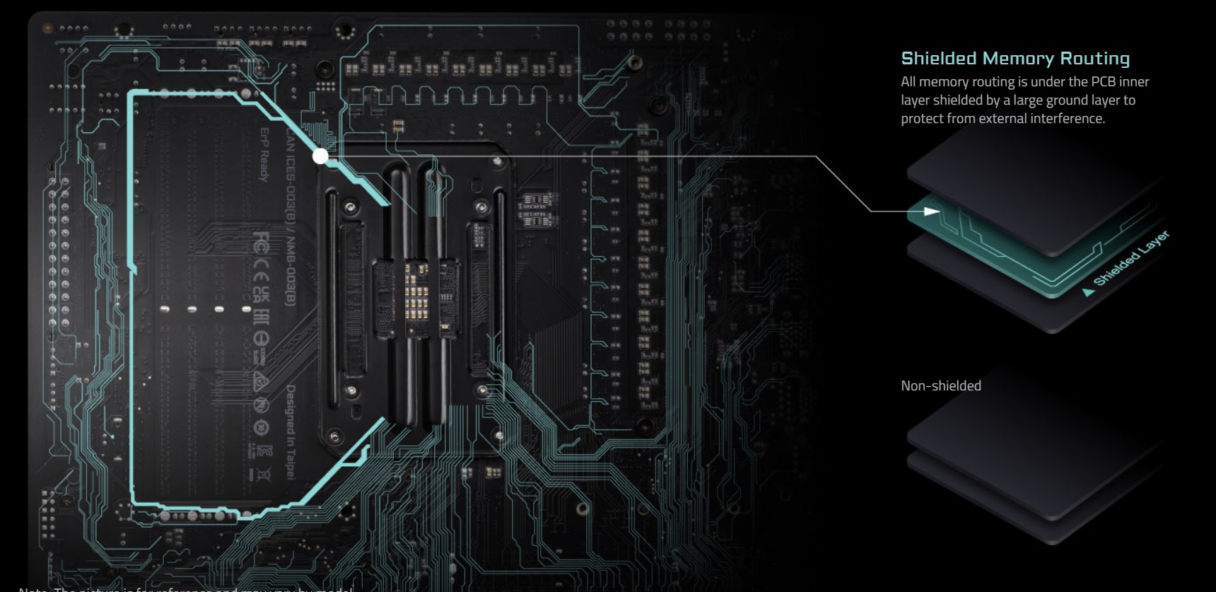 PCB Layering PCB Layering
Another key feature is the PCB layering and how GIGABYTE has separated the DDR5 circuitry. All memory running is on the inner side or layer of the PCB or in other words, sandwiched between the layers of the PCB. This level of shielding coupled with daisy-chaining routing help in reducing noise or external interference and ensures stable memory operations even under high overclocking. M.2 Ports and Thermal GuardOne of the salient features of AMD’s new platform is the support for upcoming Gen 5 base M.2 NVMe SSDs and we are seeing some jaw-dropping read/write speeds on those drives. The B650 chipset-based motherboard provides support for Gen 5 M.2 port. This motherboard has a total of 3x M.2 ports. Two of these ports are wired directly to the CPU socket whereas the two are wired to the chipset. We have got some stylish M.2 covers for these ports. 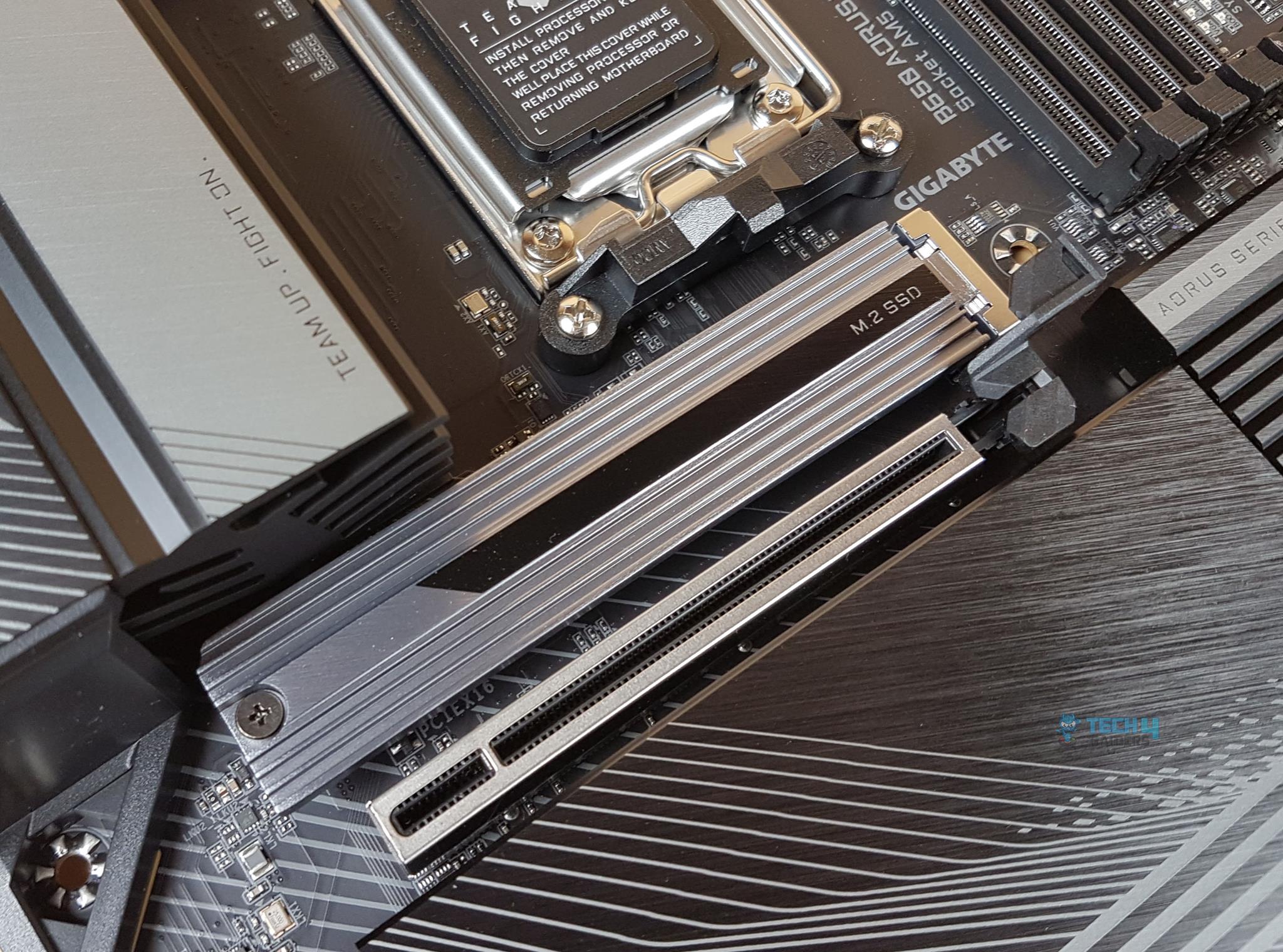 M.2 SSD Slot M.2 SSD Slot
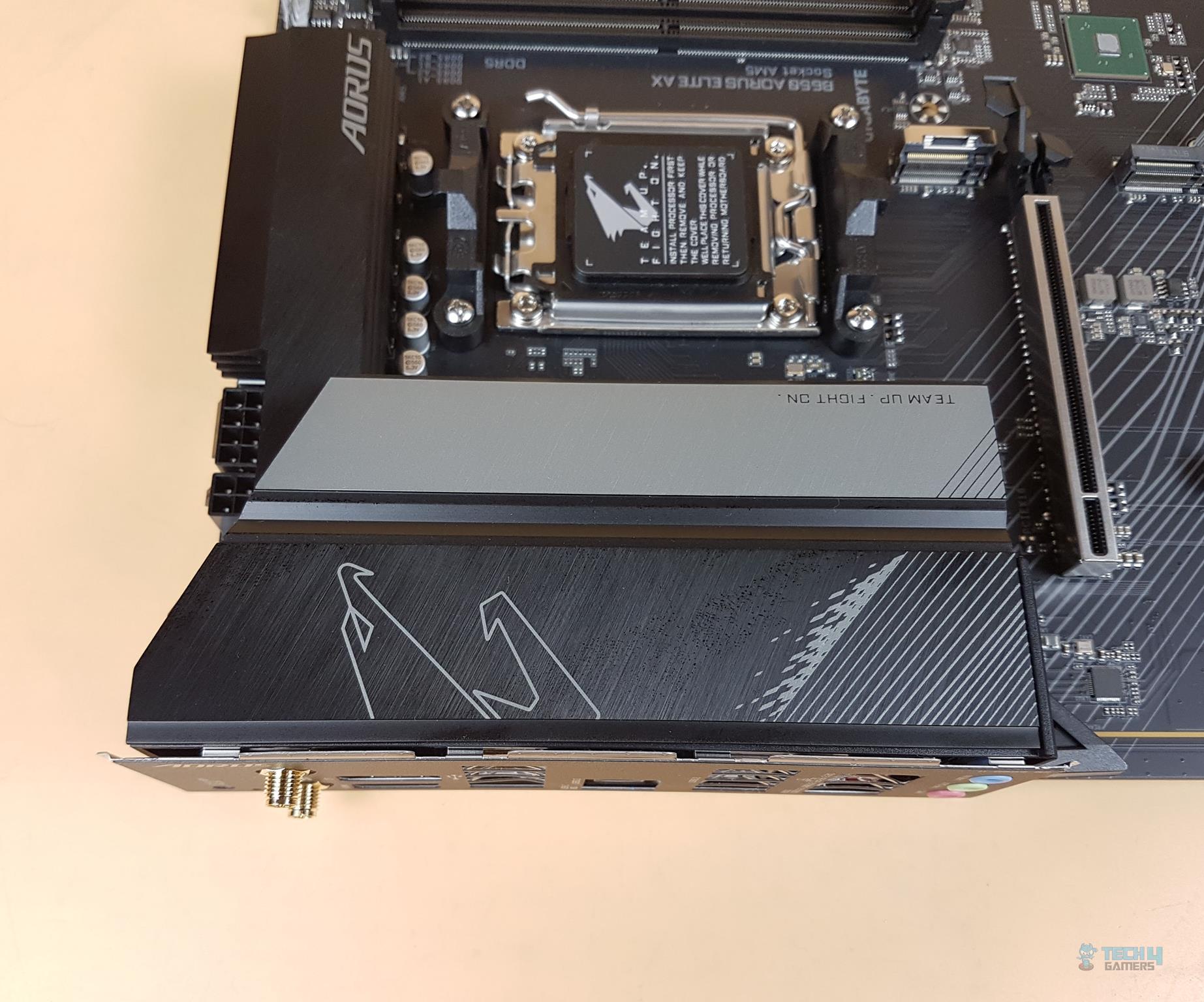
The topmost slot has a single-layer heatsink with a thermal pad underneath for efficient heat transfer. M.2 SSD is written on the cover. This cover is separated from the other covers. It can be taken off by unscrewing a Philips screw and removing the cover from the slot. 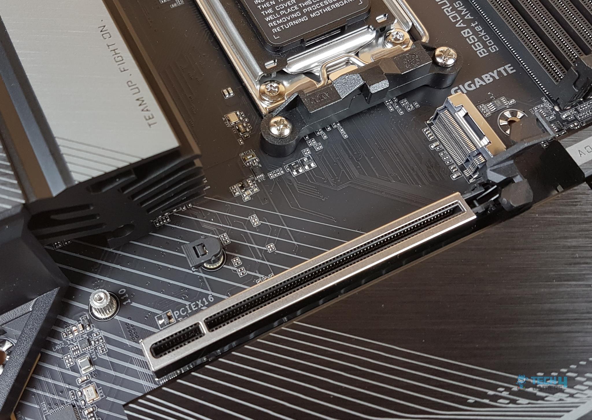 PCIe X16 Slot On GIGABYTE B560 AORUS Elite AX Motherboard PCIe X16 Slot On GIGABYTE B560 AORUS Elite AX Motherboard
The top port supports the new 25110/2280 form factor and is labeled M2A_CPU. This is a Gen 5 slot. This is the only slot on this motherboard featuring PCIe Gen 5 x4. This port features the EZ-Latch which is a tool-free way to install the M.2 SSD in the port. Say bye-bye to the screws! 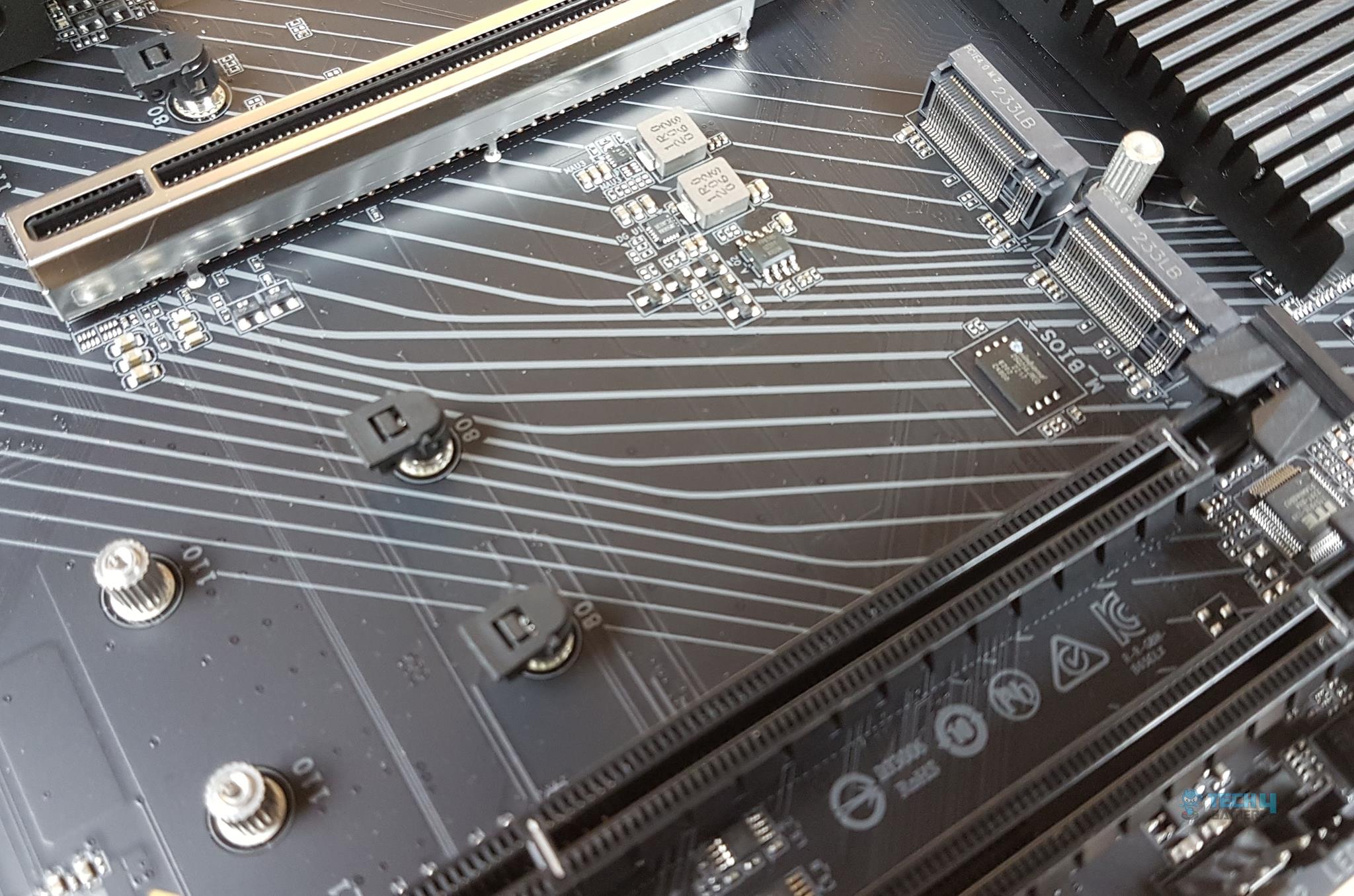 M.2 Slots M.2 Slots
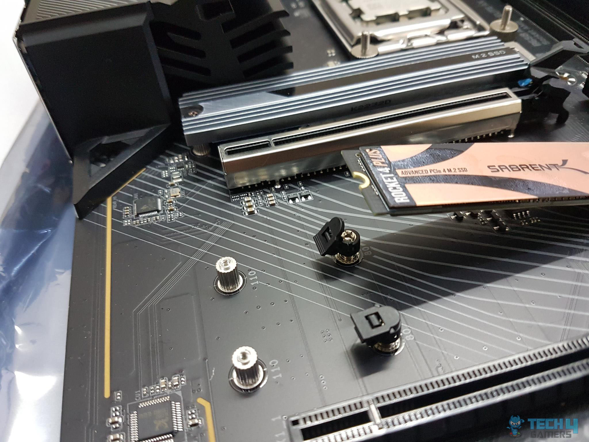
The above picture shows the 2x M.2 ports. The top slot is wired to the CPU and is labeled as M2B_CPU. The second port is wired to the chipset and is labeled M2C_SB. Both ports are Gen 4 x4 slots. These support the 22110/2280 form factors. These ports also feature the EZ-Latch mechanism making life easy.
The above picture shows the installation of the Sabrent Rocket 4 Plus 2TB Gen 4 SSD. Insert the SSD in the socket. Lift the locking tab/notch off the screw mount. 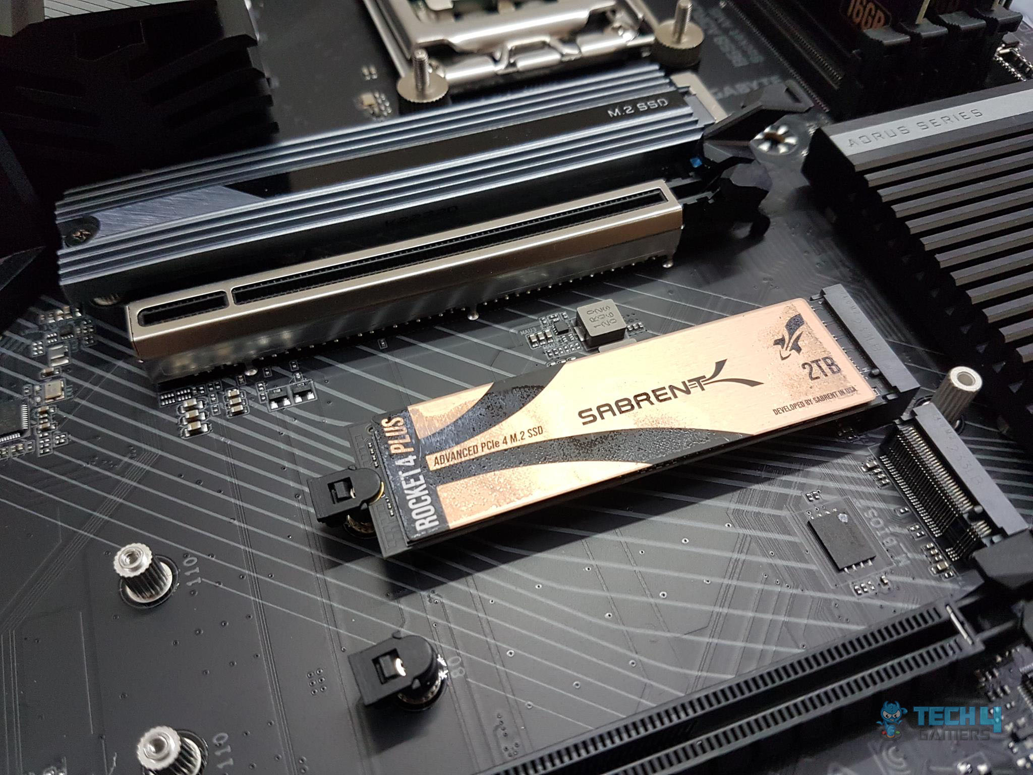 Installing SSD Installing SSD
Press the SSD gently and push the locking notch on the mounting screw. That simple! 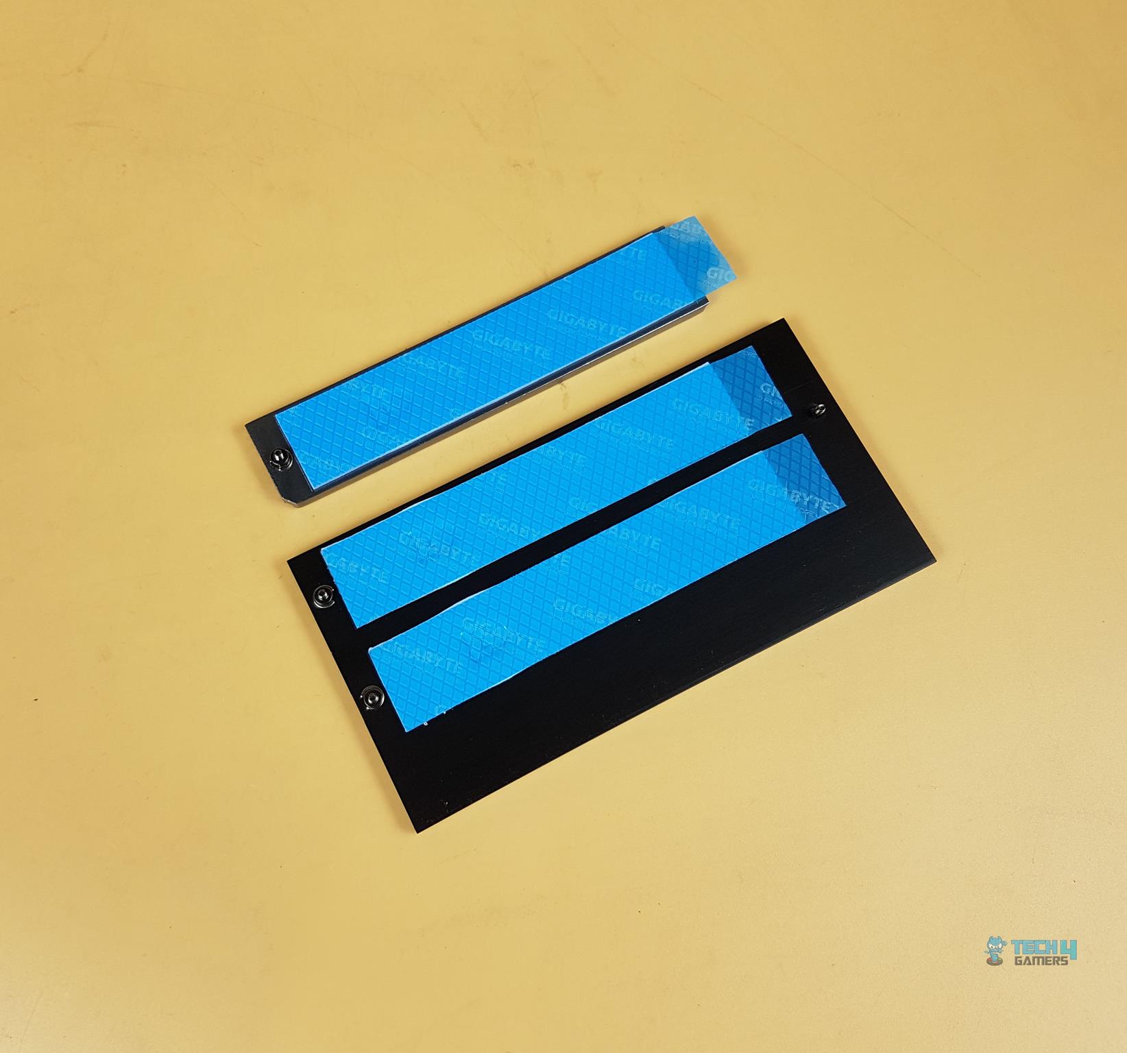 NVME SSD Covers NVME SSD Covers
The above picture shows the M.2 NVMe port covers. They are made of aluminum material and have pre-applied thermal pads. PCIe Slots and EZ-Latch DesignNow, let’s turn our attention to the PCIe slots on this motherboard. This motherboard has 3x PCIe slots.
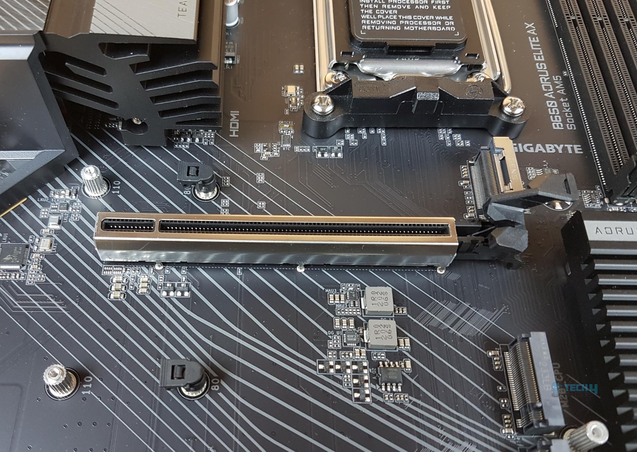
The topmost PCIe slot is wired to the CPU socket and is a fully functional PCIe Gen 4 x4 slot with a theoretical bandwidth of 64GB/s. GIGABYTE has opted to provide a Gen 5-based M.2 port in line with AMD’s specifications of the B650 chipset. This slot is SMD stainless-steel reinforced. This Ultra Durable PCIe Armor Stainless steel provides reinforced tensile strength. As we have seen on the previous GIGABYTE motherboards, this motherboard is using double locking bracket for the topmost slot. GIGABYTE has provided an extended PCIe locker which is implemented on top of the standard locker. This is what they refer to EZ-Latch which makes it convenient to remove the graphics card from the slot. Since this extended locker arm is extending the top NVMe slot, it is easier to access in otherwise the space-constrained area. 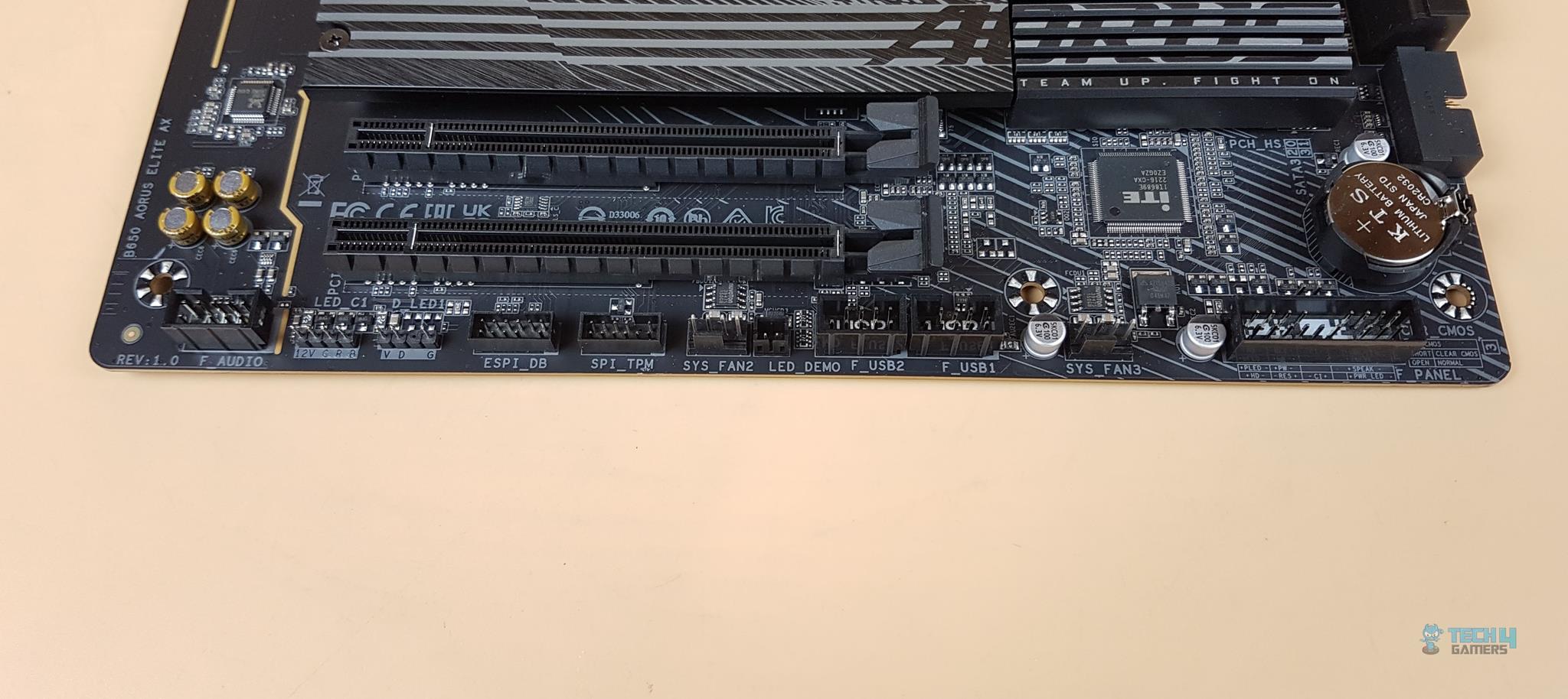 PCIe Gen 3 Slots PCIe Gen 3 Slots
There are two non-stainless steel PCIe slots. These are PCIe Gen 3 slots and both are rated at X1 speed. I am wondering about this implementation though. There should have at least been one X4-rated PCIe slot for add-in card support. Anyhow, the main reason for rating these at X1 is that they shared the single PCIe Gen 3 bus with the wireless and wired connectivity provision. I would have preferred a bit lower USB count in favor of one fully X4 PCIe slot. B650 ChipsetNow, it is time to take a look at the B650 chipset area. 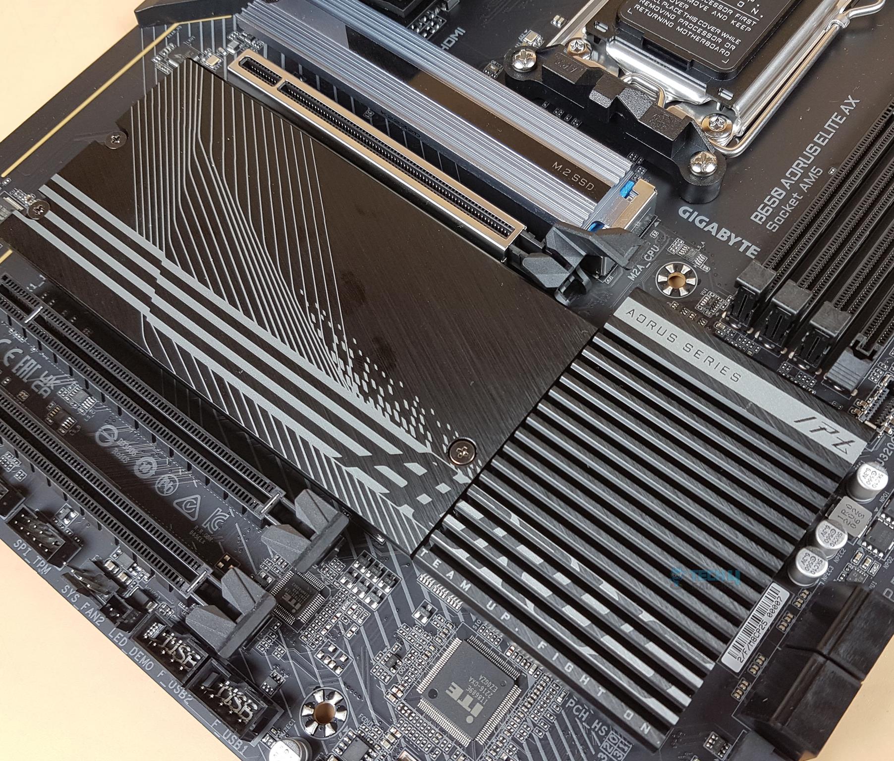 Stylish Cover Stylish Cover
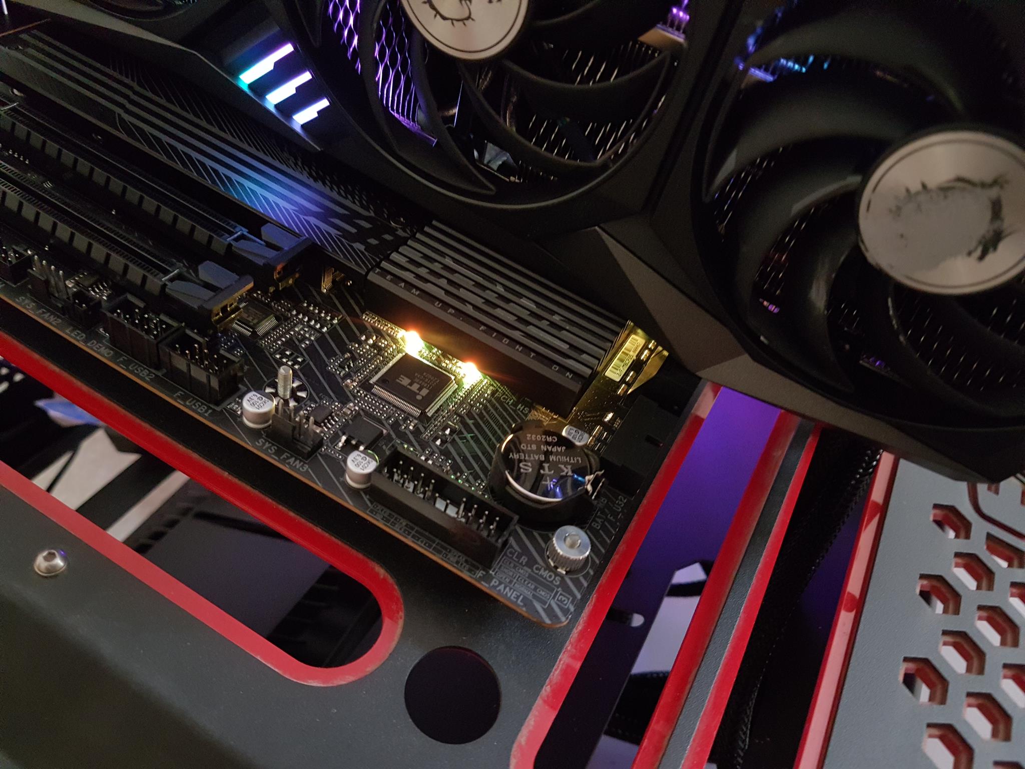
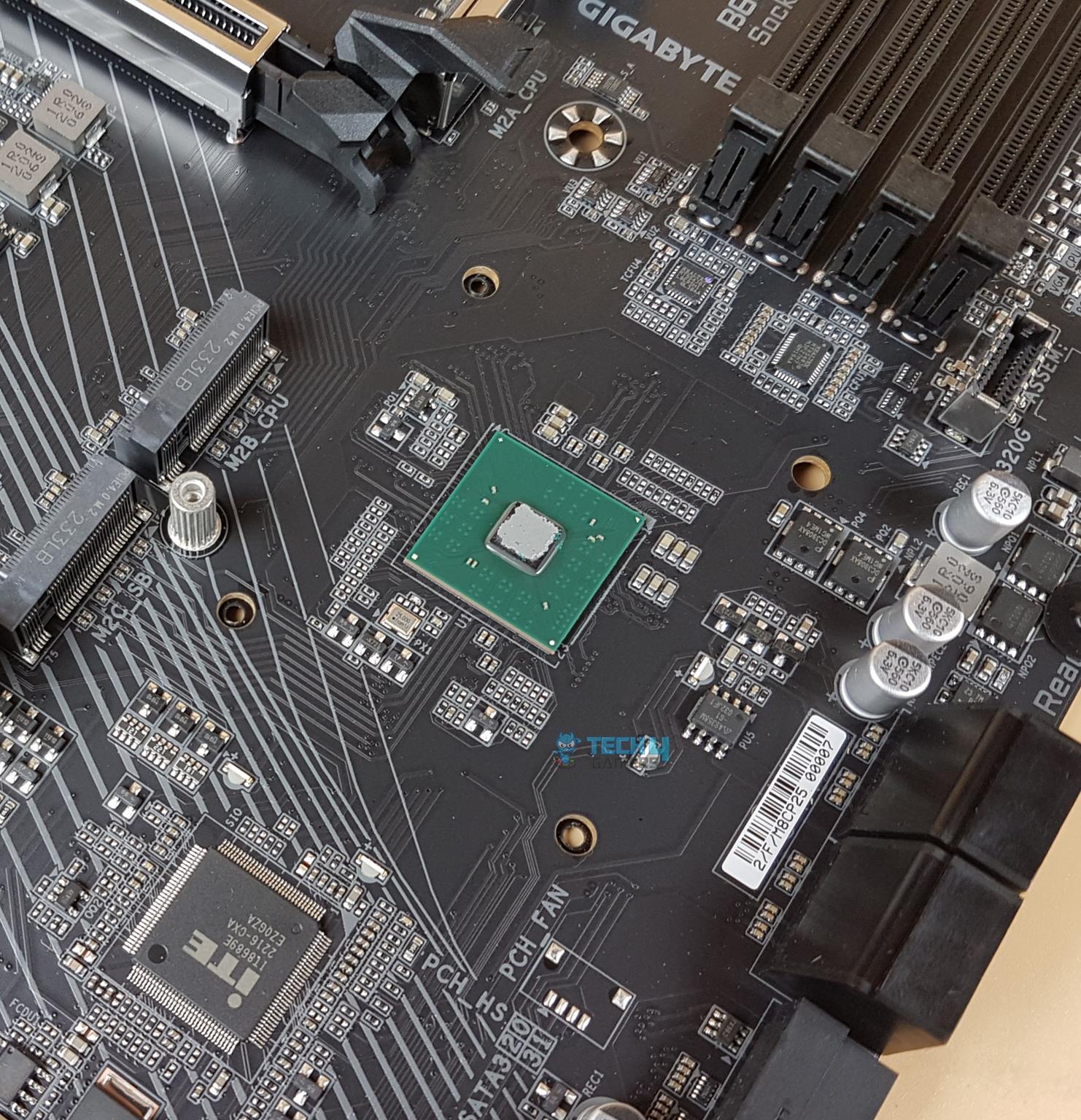
There is a slotted pattern stylish cover on the chipset area. There is a gray color stenciling on the top with AORUS SERIES printed over it. Team Up, Fight On tagline is printed at the bottom. The size of this cover is enough to tell that we have a single chipset underneath unlike the X670E. There are 4x screws on the backside of the PCB. Removing them will release the cover.
Behold the B650 chipset! We have a simple layout with a power delivery circuit on the right. I am guessing this chipset would draw near 7W or so hence we have a passive cooling for it.
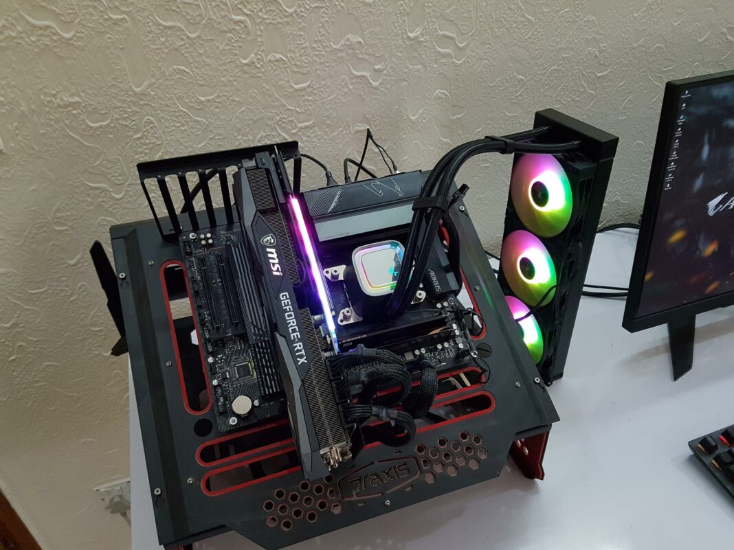
 RGB Lighting on GIGABYTE B560 AORUS Elite AX Motherboard RGB Lighting on GIGABYTE B560 AORUS Elite AX Motherboard
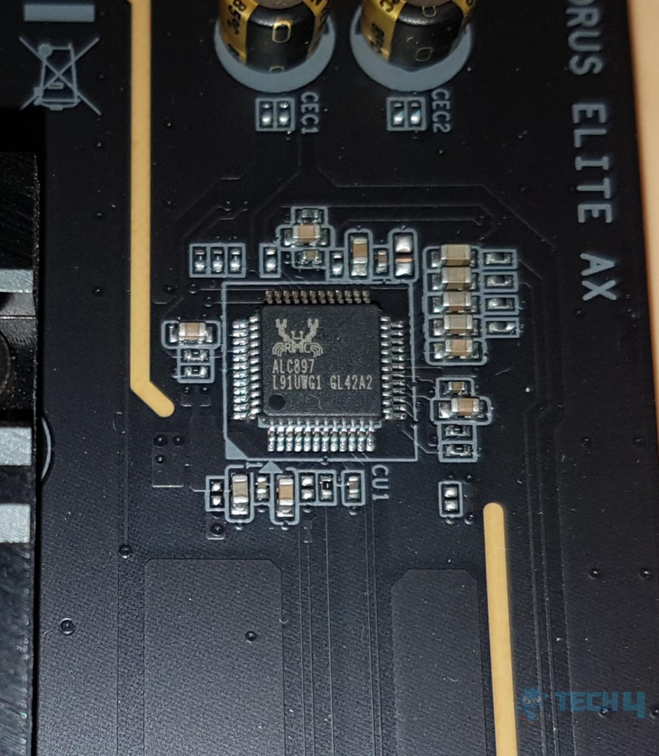
This is the only area on the motherboard with RGB lighting. Audio SolutionThe audio solution on this motherboard is pretty ordinary, using RealTek ALC897 codec to drive the audio solution. This is just an ok solution which could have been better in my opinion. 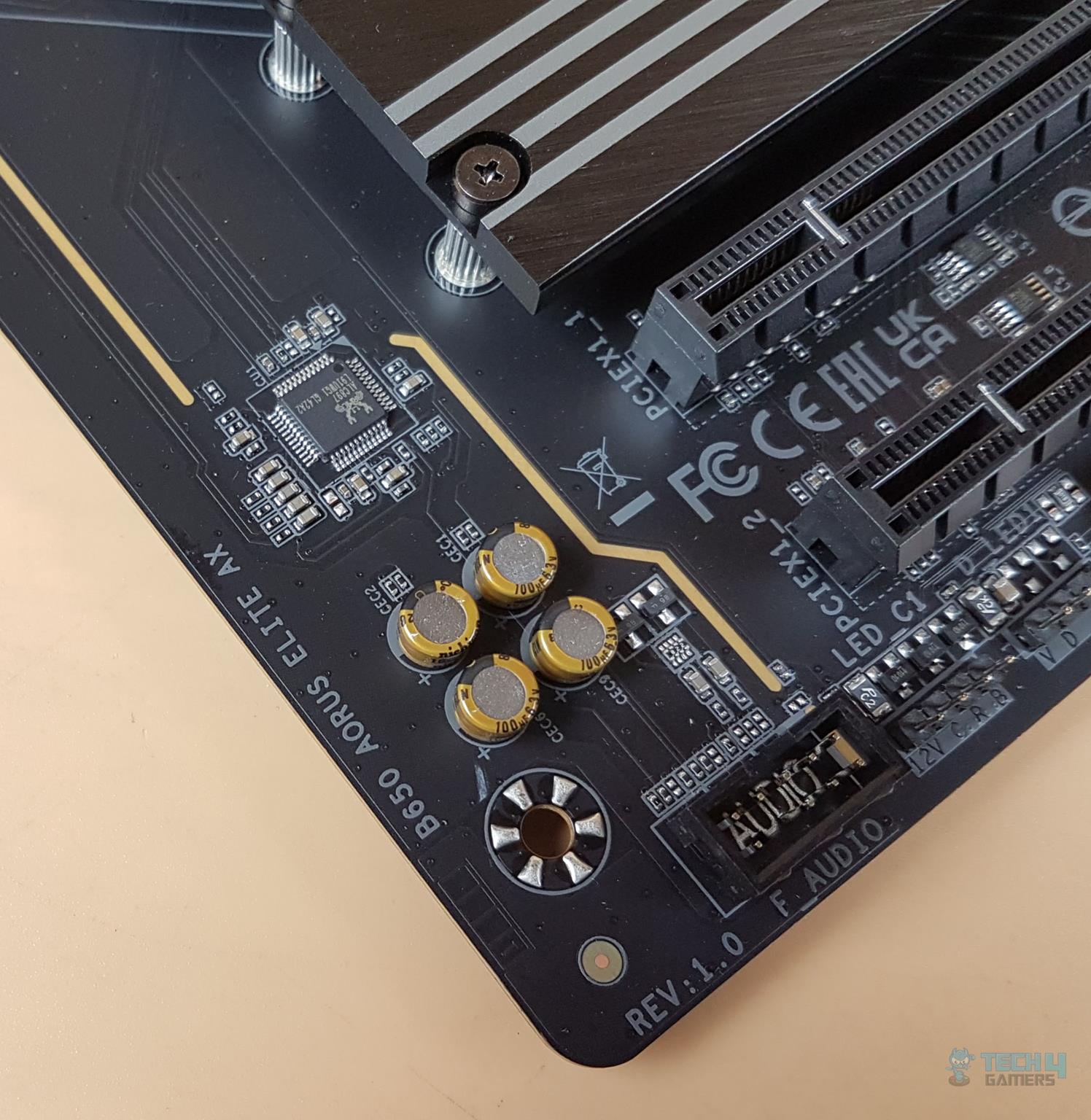 Audio Support Audio Support
The above picture shows the well-shielded Audio circuitry. This motherboard is not using high-end WIMA capacitors. We only have Fine-Gold capacitors to drive the power of the circuit. This is not a Hi-Res Audio solution. AORUS motherboards feature an audio noise guard that essentially separates the board’s sensitive analog audio components from potential noise pollution at the PCB level.
The above picture shows the ALC897-VB controller from Realtek. The onboard sound solution is not capable of delivering the DTS:X Ultrasound experience. Networking ConnectivityWe have two main areas here: Wireless connectivity Wi-Fi Bluetooth Wired connectivity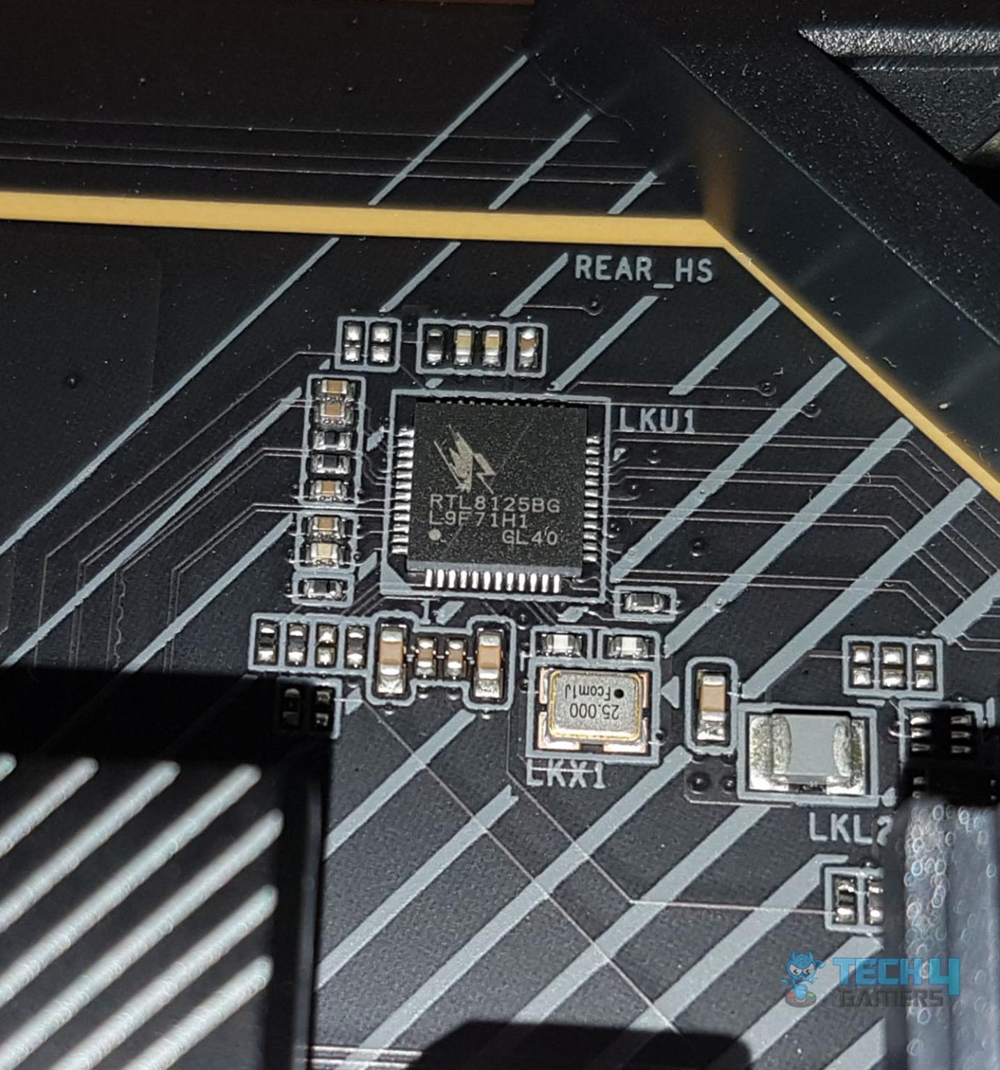 LAN Chip LAN Chip
GIGABYTE has provided a single 2.5GbE LAN chip using RealTek RTL8125BG on this motherboard. There is a single RJ-45 port on the back panel for the wired network connectivity. The 2.5GbE provide roughly double the speed of that 1GbE connectivity for a better online gaming experience. The Ethernet port supports 10/100/1000/2500Mbps. 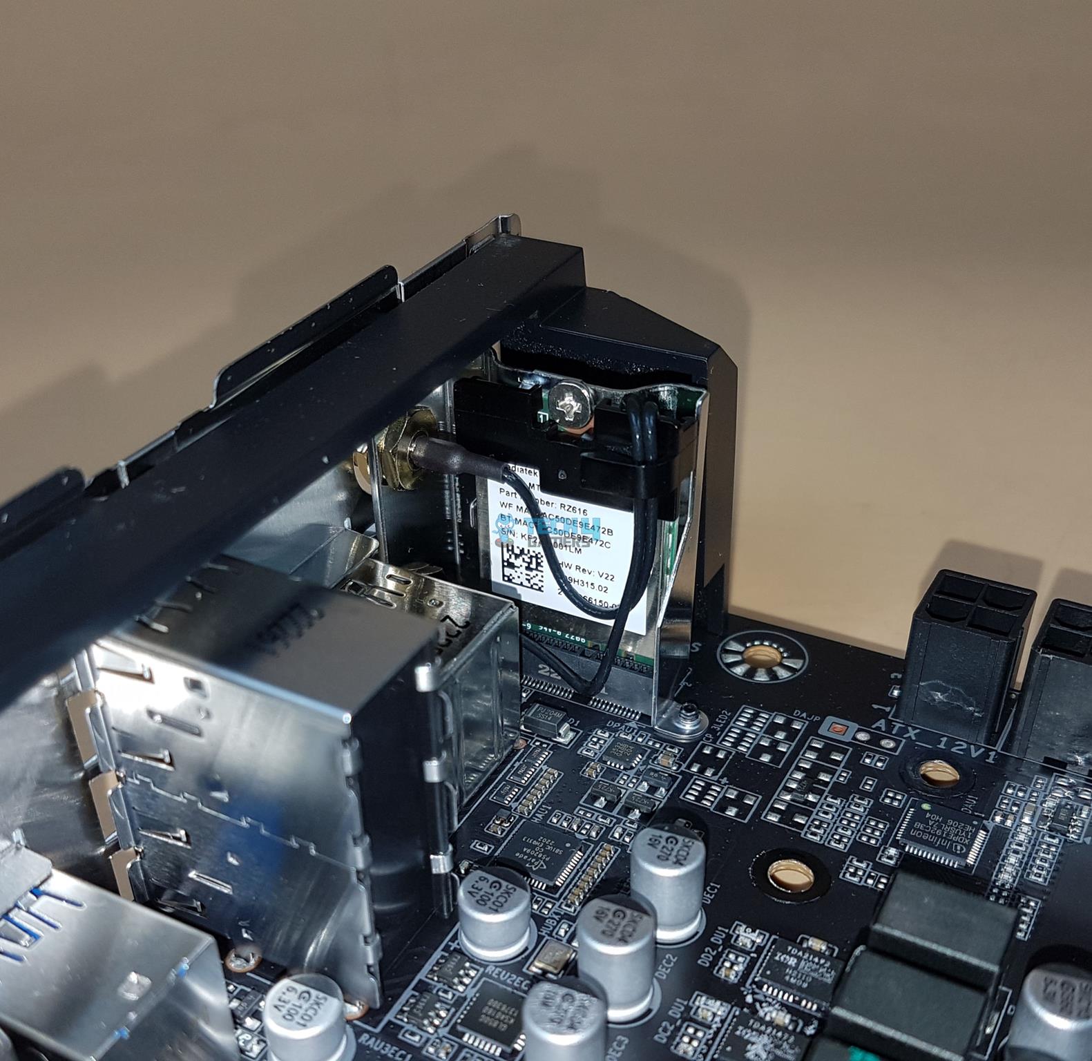 Wi-Fi Module Wi-Fi Module
The Intel Wi-Fi module is implemented on the mSATA NGGF port on the rear I/O panel. The main driving force is the MediaTek MT7922 (RZ616) chip capable of Wi-Fi 6E connectivity. The latest Wireless solution 802.11ax Wi-Fi 6E with a new dedicated 6GHz band enables gigabit wireless performance providing smooth video streaming, a better gaming experience, lesser dropped connections, and speeds up to 2.4Gbps. The motherboard features Bluetooth 5.3 protocol. Some of the key benefits of Wi-Fi 6E compared to Wi-Fi 5 are: 40% faster speed for a smoother gaming/streaming experience 50% higher resolution for video game-related content Better battery life for VR devices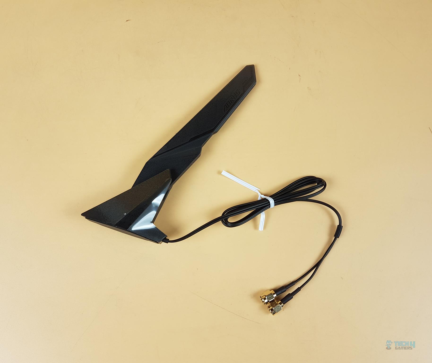 Wi-Fi Antenna Wi-Fi Antenna
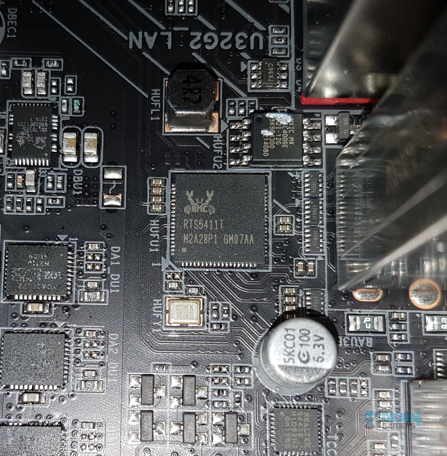
GIGABYTE has provided a Wi-Fi antenna in the box with a magnetic base for convenient mounting. USB ConnectivityFirst, we take a look at USB connectivity from the CPU socket: 1 x USB Type-C® port on the back panel, with USB 3.2 Gen 2 support 2 x USB 3.2 Gen 2 Type-A ports (red) on the back panel CPU + USB 2.0 Hub: 4 x USB 2.0/1.1 ports on the back panel
RTS5411 is an advanced USB3.0 4-port HUB controller, which integrates USB3.0 and USB2.0 Transceivers, MCU, SIE, regulator, and charger circuits into a single chip. RTS5411 is fully backward compatible with USB2.0 and USB1.1 specifications which can be operated in Super-Speed, High-Speed, Full-Speed, and Low-Speed. Now, we take a look at the USB connectivity from the chipsets: 1 x USB Type-C® port with USB 3.2 Gen 2×2 support, available through the internal USB header 3 x USB 3.2 Gen 1 ports (1 port on the back panel, 2 ports available through the internal USB header) 4 x USB 2.0/1.1 ports available through the internal USB headers Chipset+USB 3.2 Gen 1 Hub: 4 x USB 3.2 Gen 1 ports on the back panelWe can see the plethora of USB connectivity options on this motherboard. This board has USB 3.2 Gen 2×2 over Type-C interface providing a theoretical bandwidth of 20Gbps. The rear USB 3.2 Gen 2 Type-C® is capable of a 10Gbps transfer rate. Internal ConnectorsNow that we have covered the main features, functions, and design of the motherboard, let’s take a look at the internal connectors.  Internal Connectors Internal Connectors
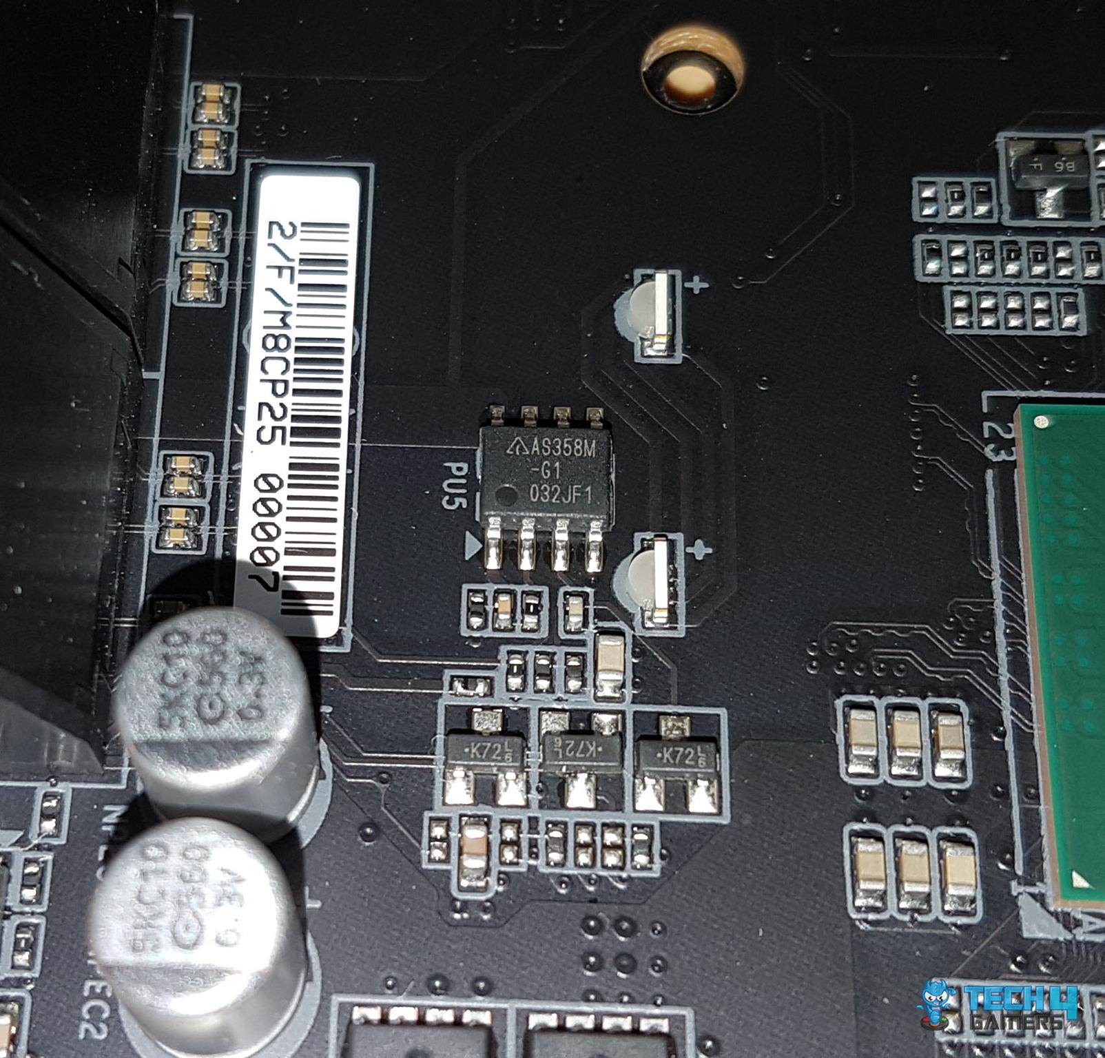
On the top of the motherboard we have: 4-Pin PWM CPU FAN Header 4-Pin PWM CPU OPT Header 4-Pin System Fan Header 2x Standard 12V 4-pin RGB Connectors 1x Standard 5V 3-pinA-RGB ConnectorAll fan headers including pump headers are rated for 2A, 24W power. 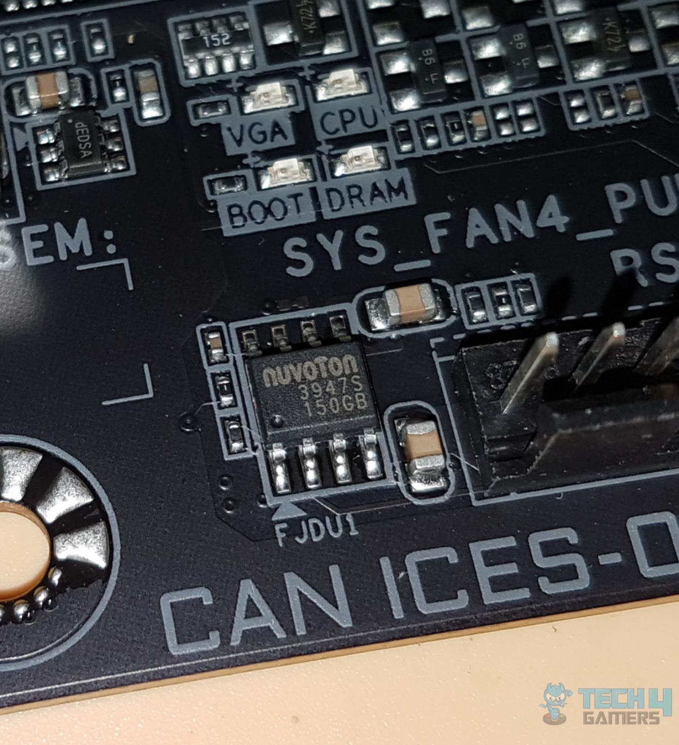 PWN Fan Headers PWN Fan Headers
GIGABYTE is using nuvoton 3947S controller for the PWM fan headers. 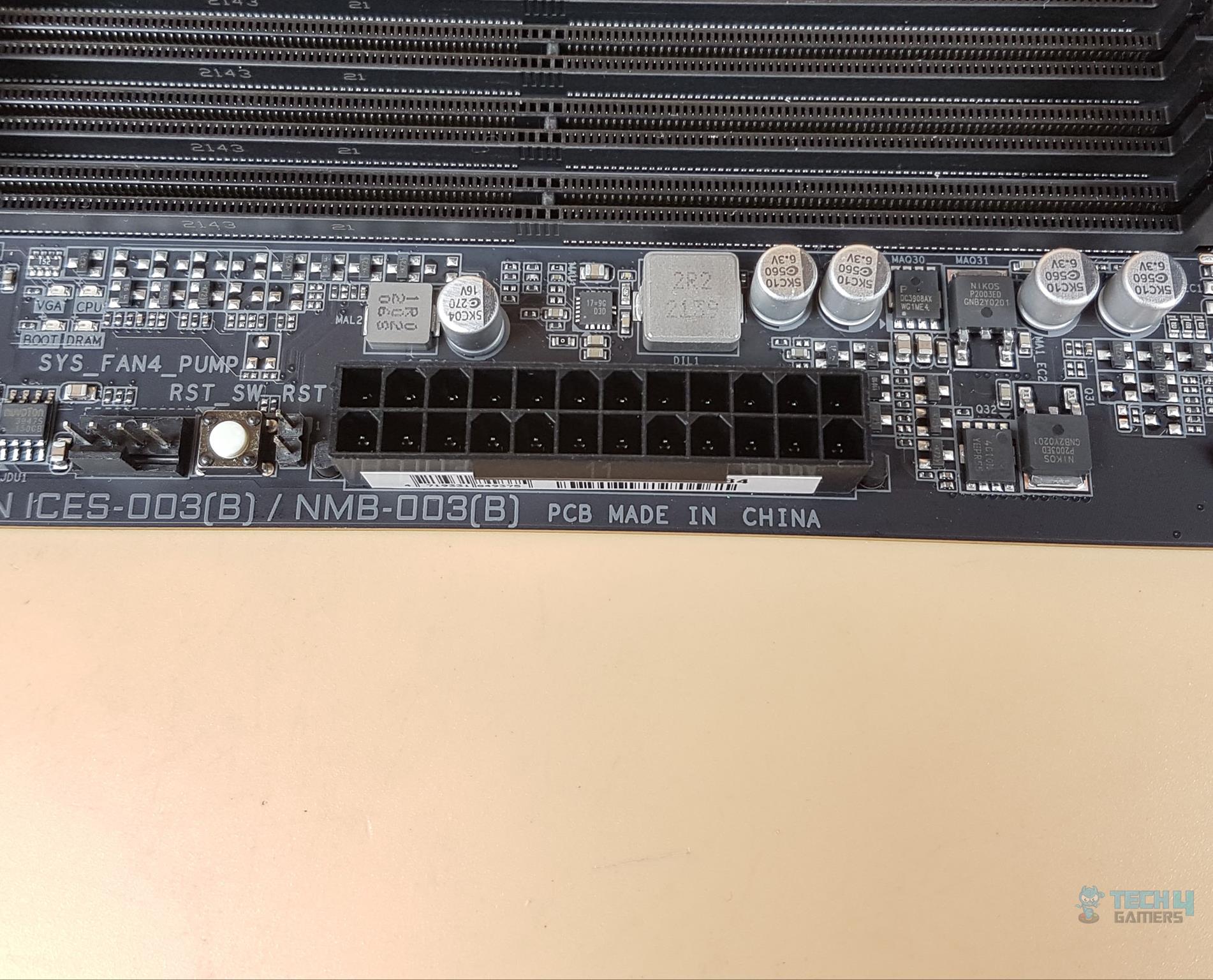 24 PIN ATX Connector on GIGABYTE B560 AORUS 24 PIN ATX Connector on GIGABYTE B560 AORUS
We have a solid pin 24-pin ATX connector here which is not stainless-steel reinforced. Top right conn We have the following: 1x 2-pin BIOS Reset Jumper 1x Reset Button 1x 4-pin PWM System Fan HeaderRST_SW button is programmable in three configurations: RGB Switch: Turn off all lighting effects on the motherboard. Direct-To-BIOS: Boot into the BIOS menu directly without pressing any keyboard button. Safe Mode: Boot into BIOS safe mode to change specific options without losing other BIOS settings.The button can be programmed in the UEFI/BIOS. There are LED indicators above. These are for the VGA, CPU, BOOT, and DRAM. They provide additional troubleshooting aid to the user above the debug LED. In case of an issue, the corresponding LED will remain lit until the issue is resolved. 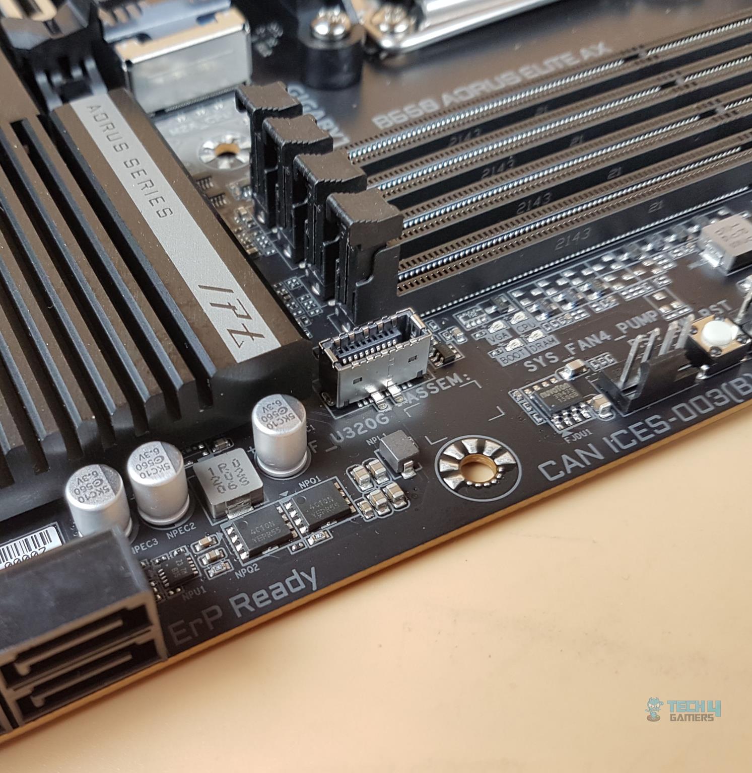 Front Panel Front Panel
Next, we have a Front Panel USB 3.2 Gen 2×2 Type-C header. 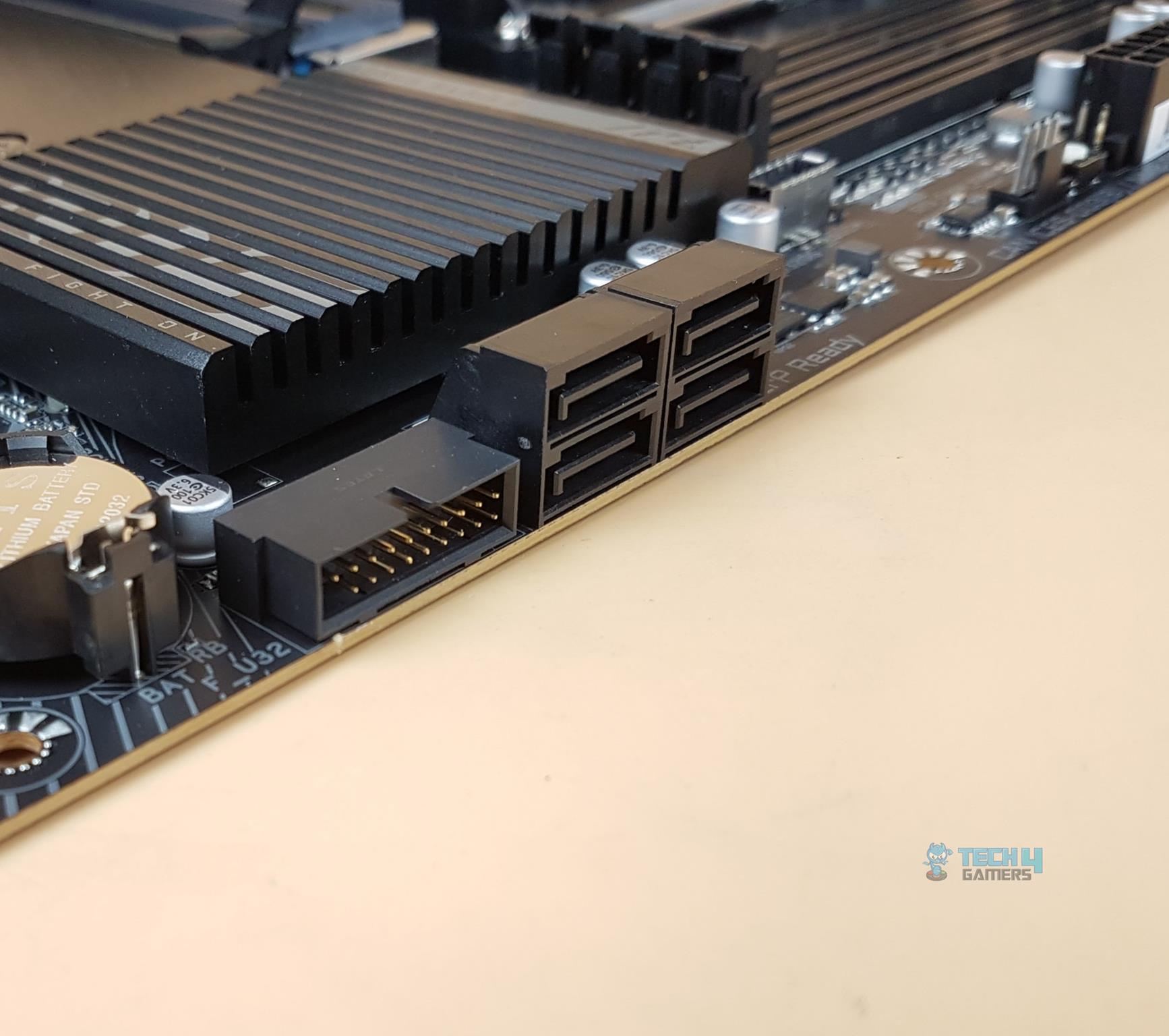 SATA Ports SATA Ports
Next, we have 4x S-ATA 6Gbps ports followed by a USB 3.2 Gen 1 header. 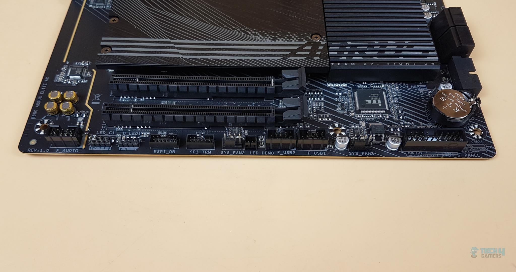 SATA Ports SATA Ports
Starting from the right side, we have: System Panel Connector 1x 4-pin PWM System Fan Header 2x USB 2.0 Headers LED Demo Button 1x 4-pin PWM System Fan Header TPM Header ESPI_DB Header 3-pin 5V RGB Header 4-pin 12V RGB Header Front Panel Audio Header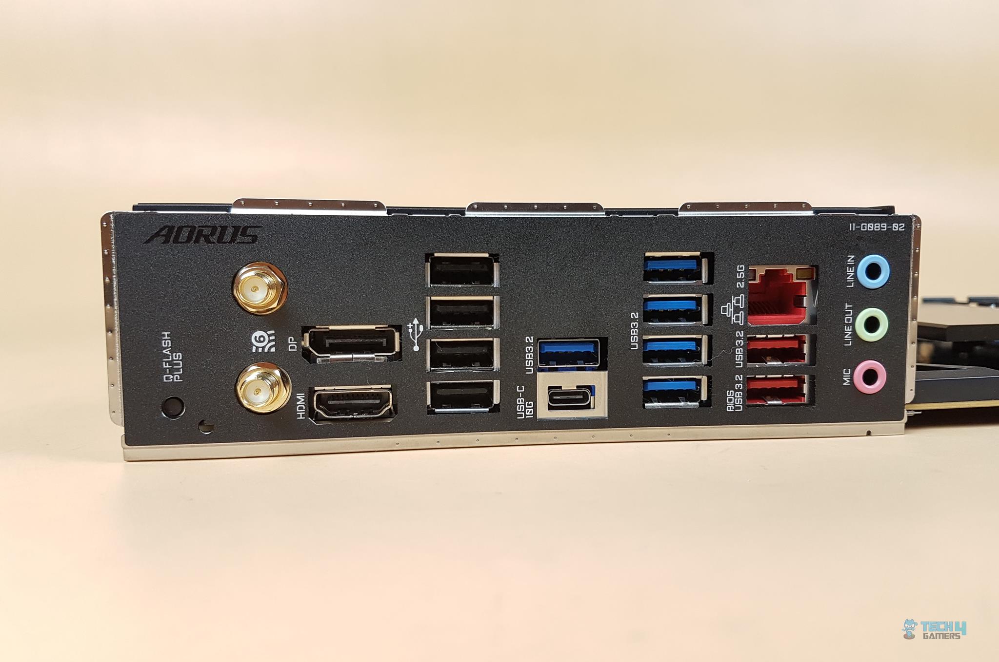 Backplate & IO of the motheroard Backplate & IO of the motheroard
This is a Rev 1.0 version of the motherboard. There will also be a Rev1.1 motherboard that The following options are provided: 1 x Q-Flash Plus button 2 x SMA antenna connectors (2T2R) 1 x DisplayPort 1 x HDMI port 1 x USB Type-C® port, with USB 3.2 Gen 2×2 support 2 x USB 3.2 Gen 2 Type-A ports (red) 5 x USB 3.2 Gen 1 ports 4 x USB 2.0/1.1 ports 1 x RJ-45 port 3 x audio jacksThe Q-Flash Plus allows the user to update the BIOS of the motherboard without installing the CPU/RAM etc. There is a Q-Flash LED Indicator on the top of the button. A USB 3.2 Gen 2 Type-A port is dedicated to the Q-Flash Plus BIOS update. There is a BIOS word written on its label for easy identification. The user would need to download the BIOS file from the GIGABYTE website. Rename it to GIGABYTE.BIN and copy it to a FAT 32 formatted USB flash drive. Connect the USB to the above-mentioned port. Connect the 12V and 24V connectors from the PSU to the motherboard. Turn the PSU on and press the Q-Flash Plus button. The LED will start blinking fast indicating that it is searching for the BIOS file. Once the BIOS flashback is completed the LED will turn off and the PSU will shut down and restart. The BIOS is updated. 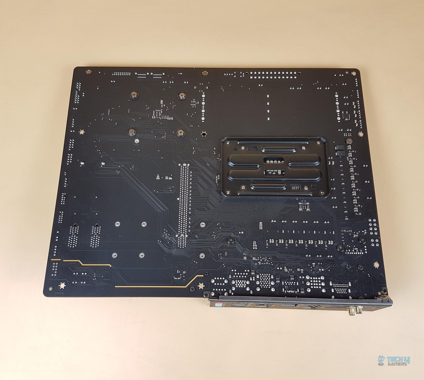 The backside of the Motherboard The backside of the Motherboard
The above picture shows the backside view of the motherboard. There is a non-removable AMD backplate over the top. The chipset screws have rubber washers between them and the PCB. 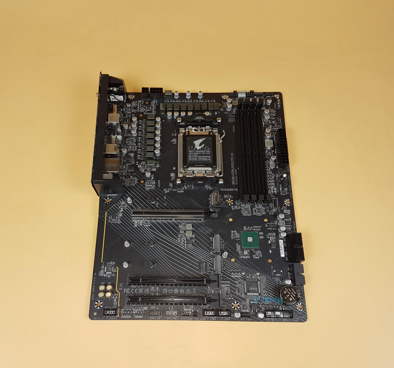 GIGABYTE B560 AORUS Elite AX Motherboard GIGABYTE B560 AORUS Elite AX Motherboard
The above picture shows the PCB with all heatsink covers removed. 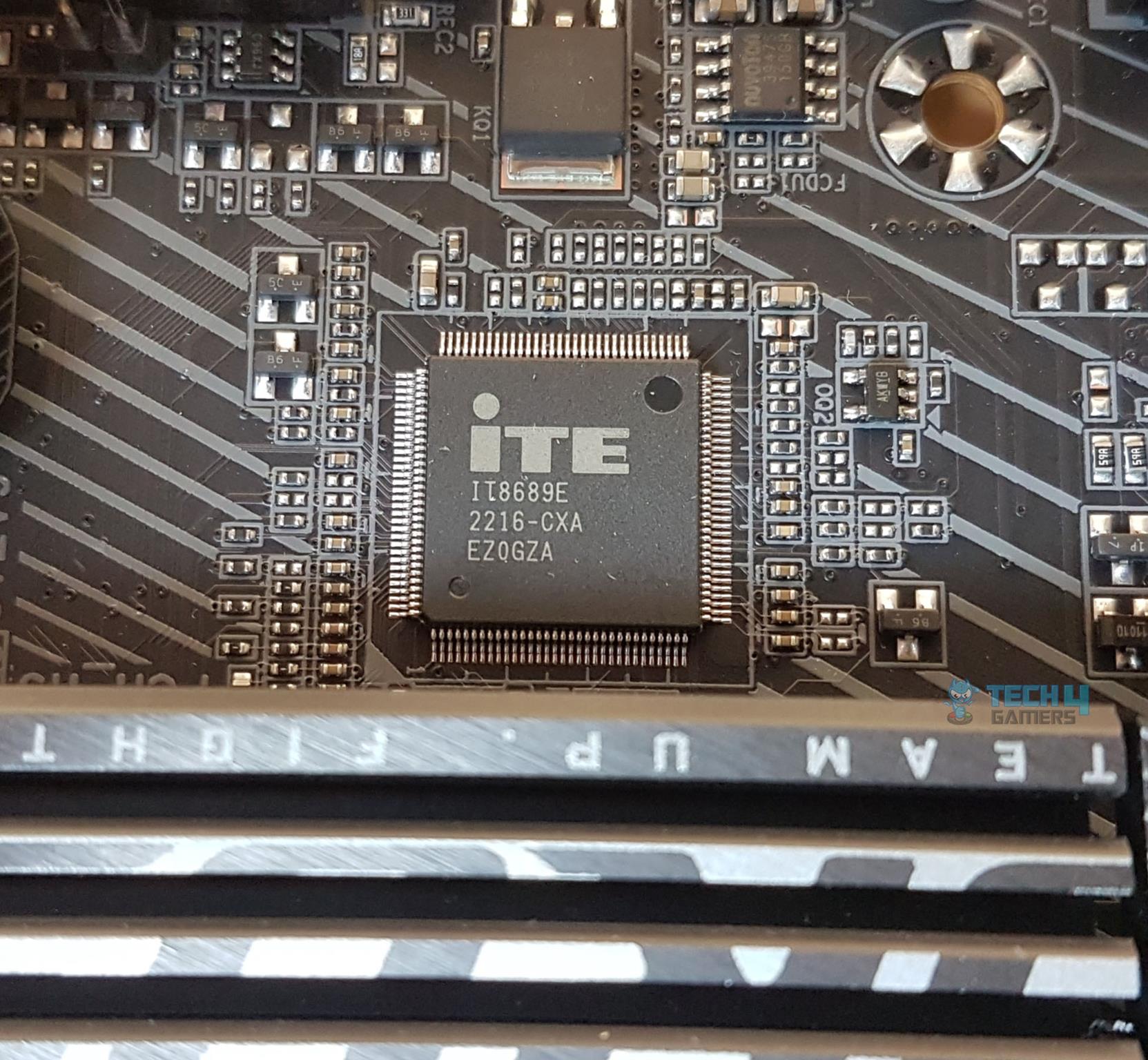 I/O Control Chip I/O Control Chip
We have an iTE8689E chip for I/O control. 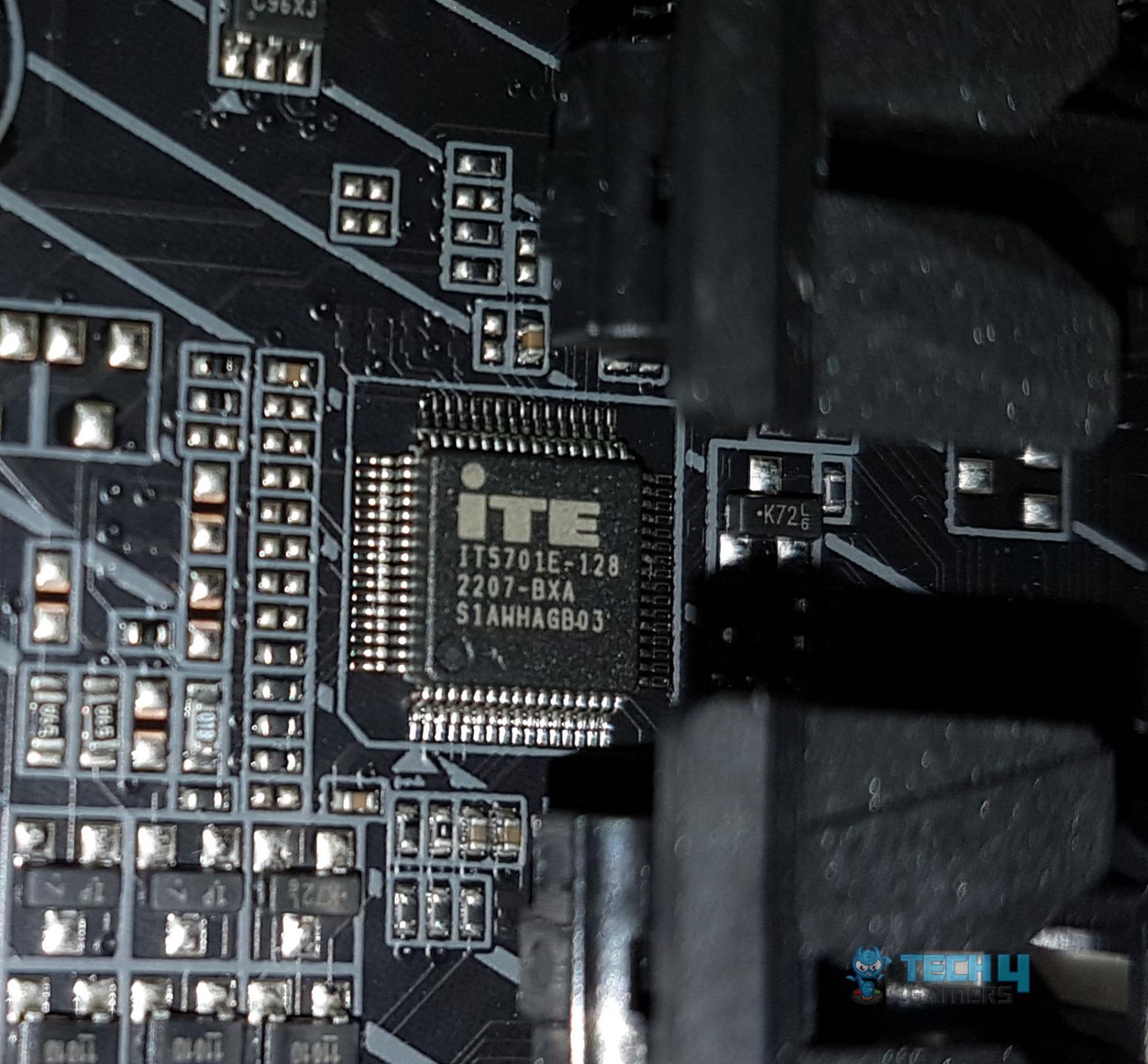 IT5701E controller is probably for the Q FLASH PLUS and RGB. IT5701E controller is probably for the Q FLASH PLUS and RGB.
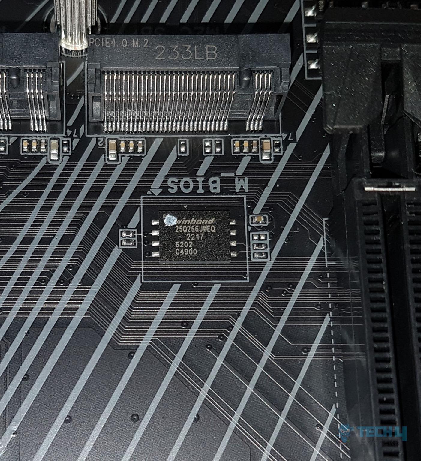
This motherboard is using 1 x 256 Mbit flash chip from winband which supports PnP 1.0a, DMI 2.7, WfM 2.0, SM BIOS 2.7, and ACPI 5.0.
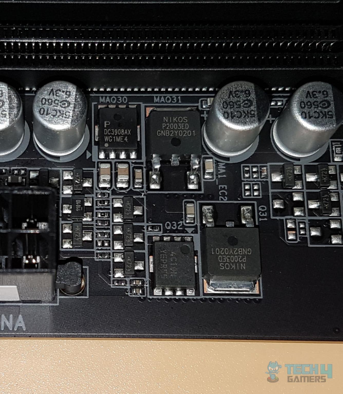
There are 2x NIKOS P2003ED coupled with 4C10N MOSFETs which are N-Channel rated at 30V, 46A. Then there is a PDC3908AX MOSFET in what seems to be a 3-high, 1-low configuration. UEFI/BIOS 1 of 15 Pressing F3 will load a menu asking to save the fan settings in the BISO or on the external media. This can be retrieved regardless of the BIOS changes later on.
 The Smart Fan 6 has some quite good changes. Now, we have Slope and Step modes available. We can set the fan to run at full speed with one click and we can set it to manual and define a custom fan curve which can be applied to the other fan headers as well.
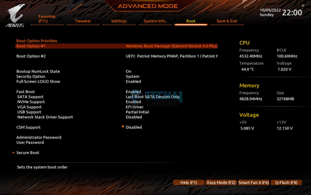
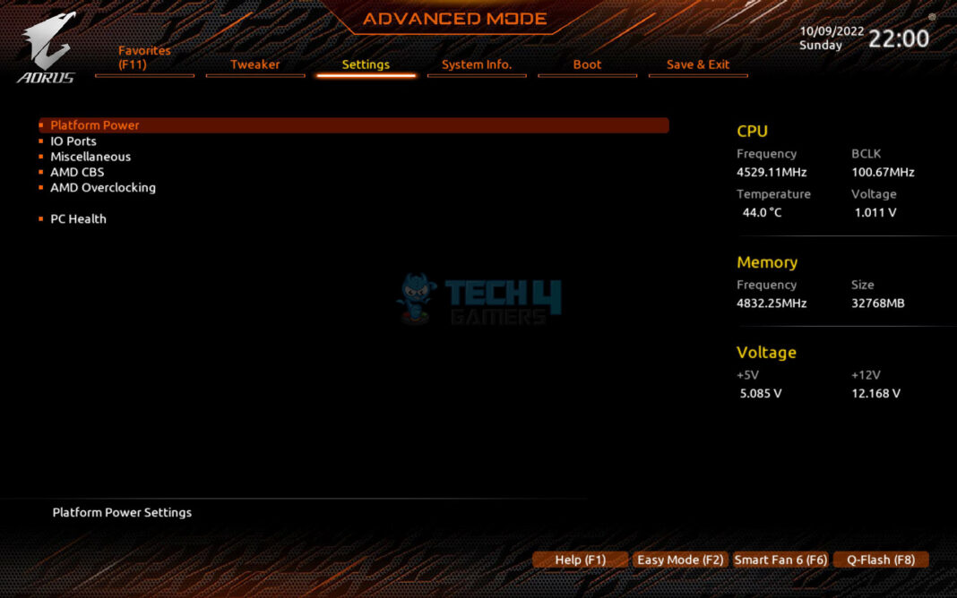
 The boot-related options are provided on this page. We have disabled the CSM so that the enabled Re-Size BAR feature can be put into use.
 The System information is provided on this page.
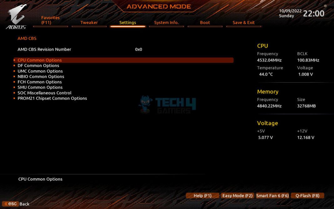
 The AMD CBS options can be accessed on this page.
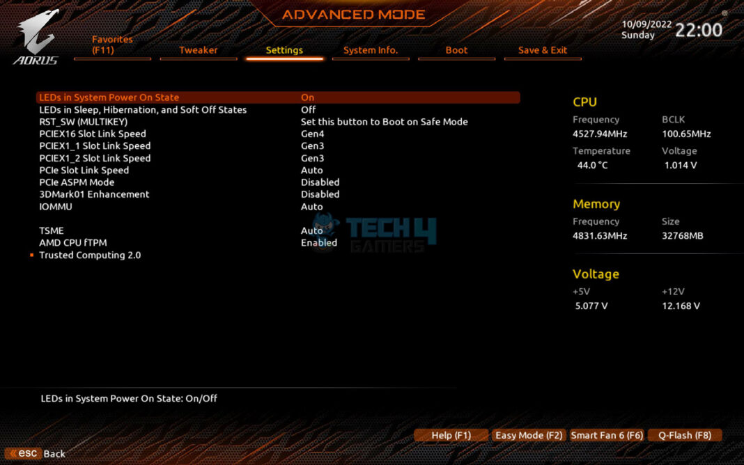
 The PCIe link speeds can be set on this page. The AMD CPU fTPM is enabled by default. This is TPM (Trusted Platform Module) required for Windows 11 compatibility.
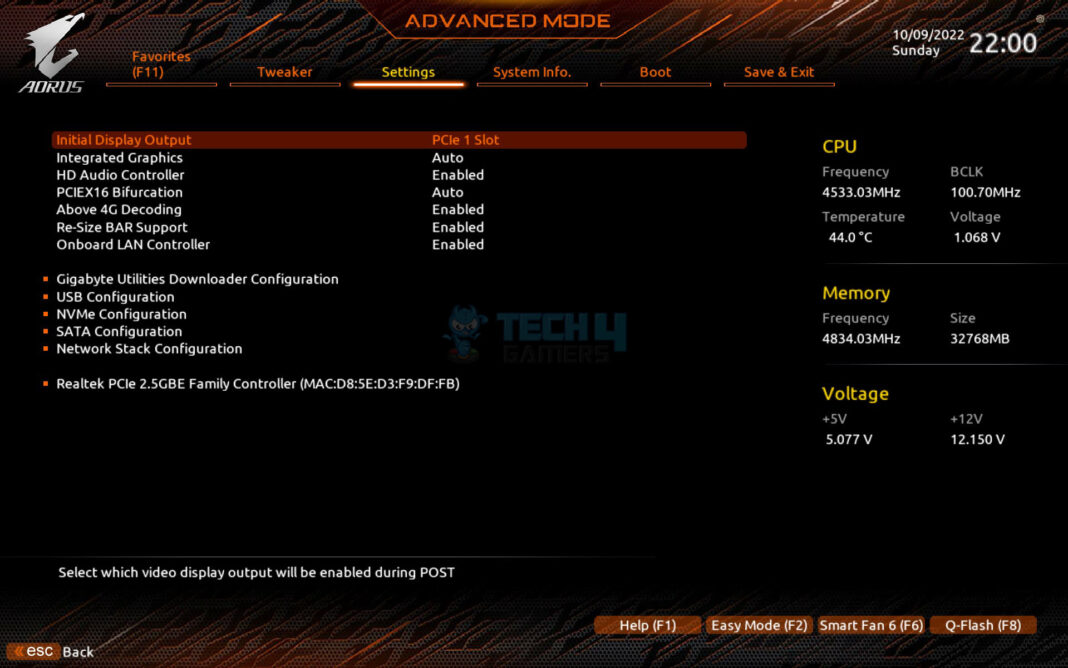
 The Above 4G Decoding and Re-Size Bar are enabled by default. If you want to utilize the GIGABYTE Control Center, then better leave the Gigabyte Utilities Downloader Configuration enabled.
 The user can define custom profiles in the BIOS and save them for later use on even use on another motherboard.
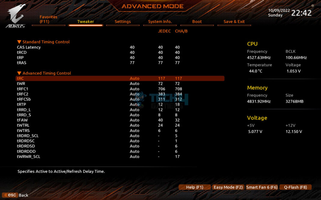
 The memory sub-timings can be adjusted from here.
 We no longer have a dedicated DDR5 voltage on the main Tweaker page. You would need to set the right voltage on this page.
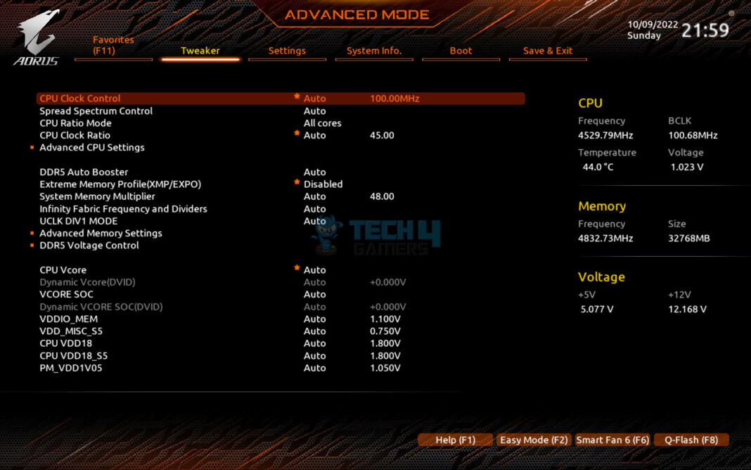
 These are CPU advanced-level settings. AMD’s famous PBO can be accessed from here.
 Note: It is better to leave Infinity Fabric Frequency and Dividers on Auto as with AM5 the game is different. Infinity Fabric will adjust automatically according to the Memory Clock (MCLK). But you need to focus on the Main Memory to Memory Controller clock as it still needs to be in a 1:1 ratio that is if the MCLK is 4800 then the UCLK would be half of it. UCLK DIV1 MODE is by default on Auto and it will work just fine though you can change it as per the requirement.
 The BIOS is loaded in the Easy mode where the summary and current statistics are shown of the components.
 We have more or less the same interface and layout as we have seen in the past from GIGABYTE.
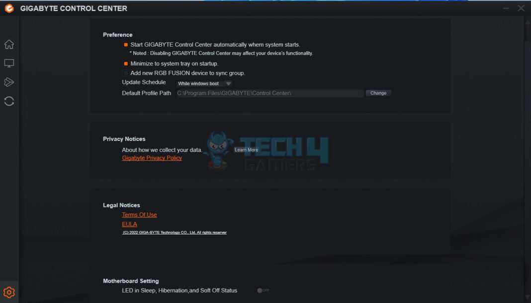
The last page is the Save and Exit options. The user can define the profiles and load them later on. The optimized Defaults can also be loaded from here. GIGABYTE Control Center GIGABYTE AORUS Software 1 of 6 GIGABYTE has followed the industry trend and has now merged all the related utilities under one roof called GCC. As soon as the Windows is loaded, you will be presented with an option to download the GCC. Please note that it is not yet available on the website so your only chance is to download it when given the option.
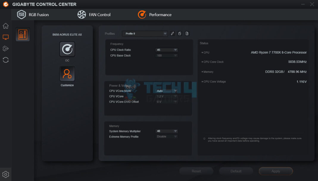
 The user can tune the system from here (but at their own risk).
 The user can define and control the fans’ behavior completely from here.
 The RGB Fusion has almost the same layout as it was in the standalone version before. The B650 AUROS ELITE AX has 5 RGB/A-RGB headers but the interface provided only four. Remember, the onboard lighting solution is RGB (not digital). So, if you decide to sync all, the digital elements will also come in RGB mode.
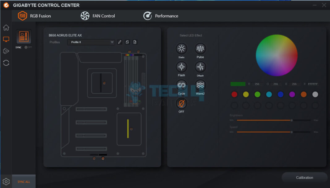 This is the main interface showing the motherboard and presents two options: RGB Fusion FAN Control
 When launched, it will present you with the available updates and utilities. You can select which ones you need and start downloading them. They will be installed automatically.
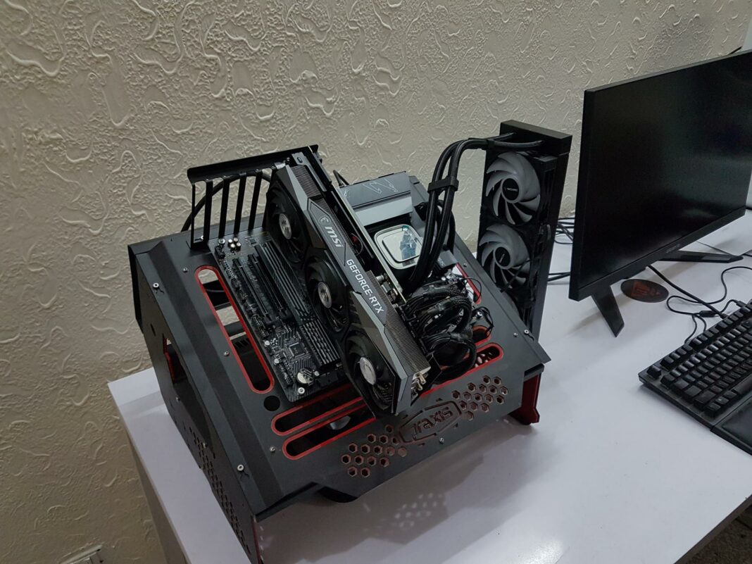
Now that we have covered the UEFI/BIOS and GIGABYTE Control Center, let us turn to the testing of the motherboard. Test SetupThe following test bench setup is used to test the performance of the motherboard: 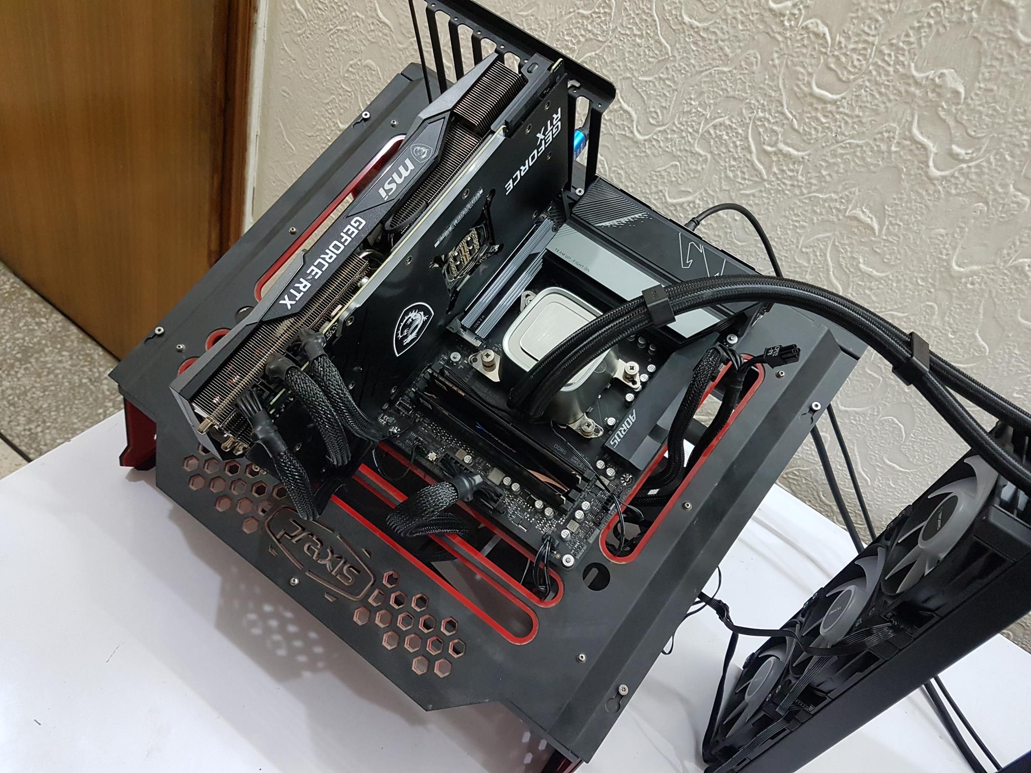 Testing the GIGABYTE B560 AORUS Elite AX Motherboard
AMD Ryzen 7 7700X [Auto, Stock]
DeepCool LS720 [Fans and Pump at full speed]
Sabrent Rocket 32GB DDR5 @ 4800MHz
MSI GeForce RTX 3090 Gaming X Trio
be quiet! Straight Power 11 1000W Platinum
Sabrent Rocket 4 Plus 2TB PCIe 4 NVMe SSD
Samsung 840 EVO 1 TB SSD for the Games
Praxis Wetbench
2x SilverStone Air Penetrator 120SK A-RGB fans Testing the GIGABYTE B560 AORUS Elite AX Motherboard
AMD Ryzen 7 7700X [Auto, Stock]
DeepCool LS720 [Fans and Pump at full speed]
Sabrent Rocket 32GB DDR5 @ 4800MHz
MSI GeForce RTX 3090 Gaming X Trio
be quiet! Straight Power 11 1000W Platinum
Sabrent Rocket 4 Plus 2TB PCIe 4 NVMe SSD
Samsung 840 EVO 1 TB SSD for the Games
Praxis Wetbench
2x SilverStone Air Penetrator 120SK A-RGB fans
Microsoft Windows 11 x64 Pro version 22H2 was used for all the testing. Nvidia 517.48 drivers were used for graphics card testing. 1 of 6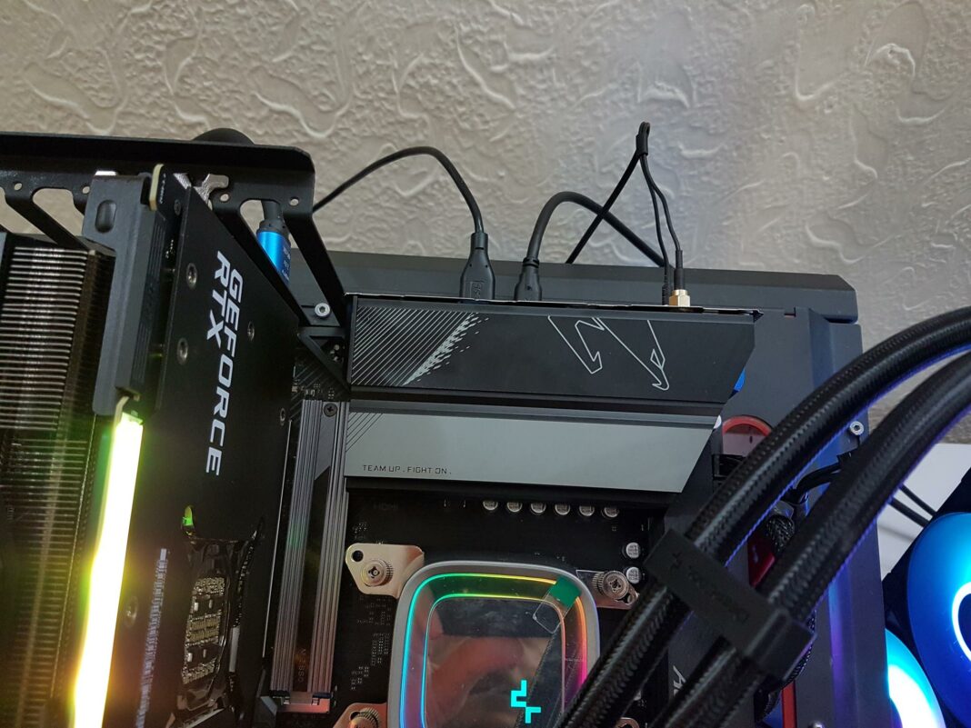

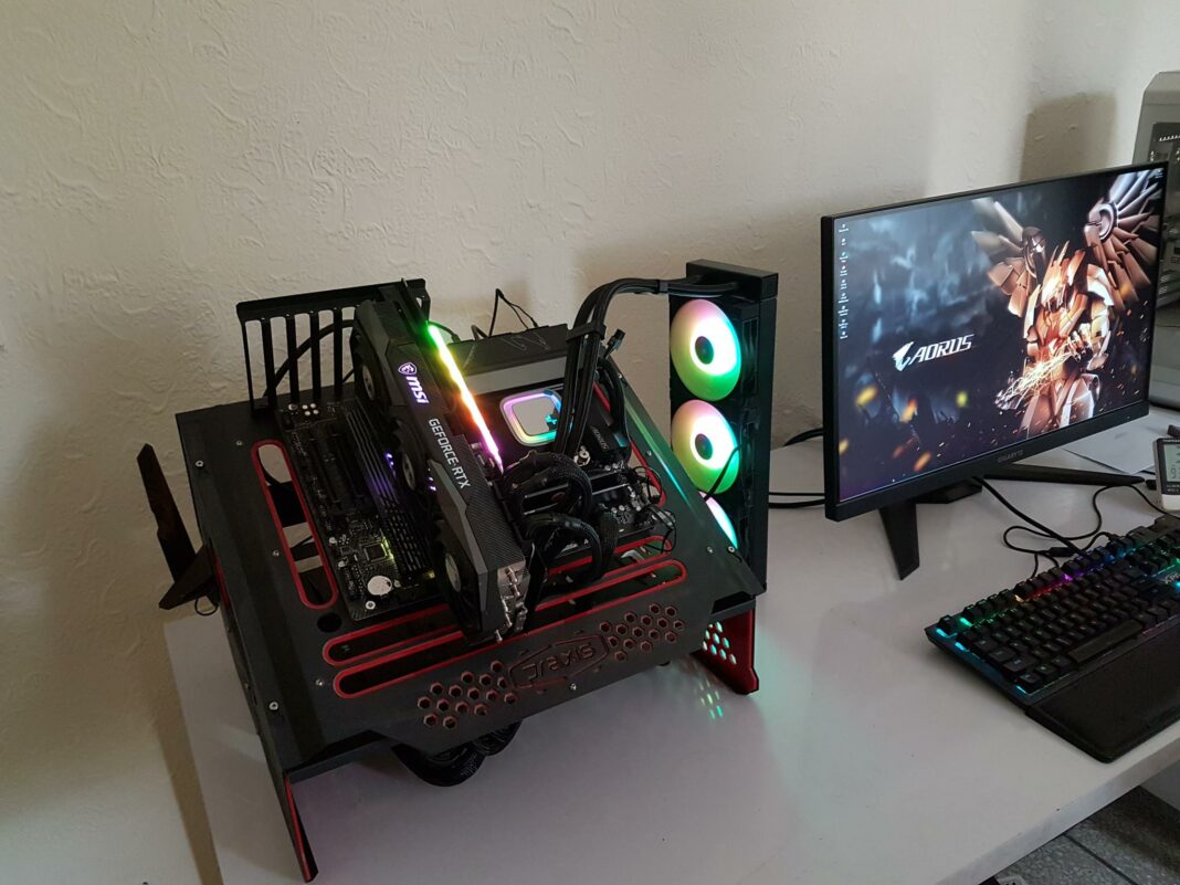 PC Building - Image taken by Tech4Gamers.

Following is the test suite: – Storage Drive Tests ATTO Crystal Disk Mark 3DMARK Storage Test CPU Tests Cinebench R23 CPU Profile GeekBench 5 7-Zip Hyper Pi AIDA64 Engineer Memory Tests AIDA64 Engineer Overall System Tests PCMark10 Performance Test User BenchmarkFor gaming and synthetic bench are used: 3DMARK Red Dead Redemption 2 Control DOOM Eternal Battlefield V Far Cry 5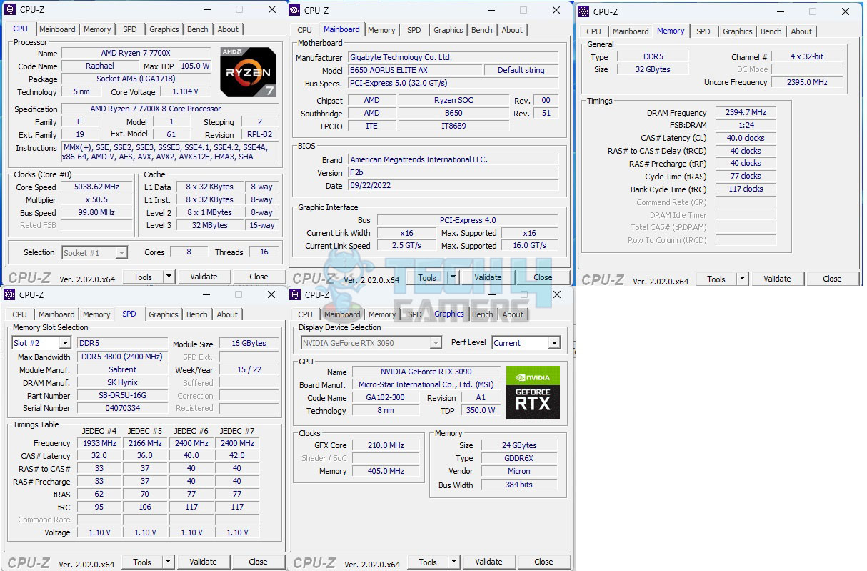 CPU-Z Scores CPU-Z Scores
The above picture shows the CPU-Z values of the platform. Overall System PerformanceThis section will show the results of the various test suites and gaming benchmarks that we have run on this motherboard. PCMark10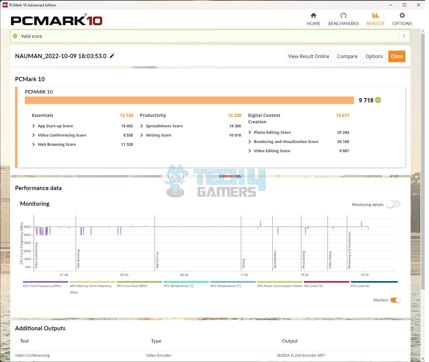 PCMark10 Scores
Performance Test PCMark10 Scores
Performance Test
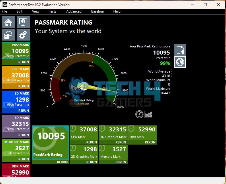 Performance Test Scores
User Benchmark Performance Test Scores
User Benchmark
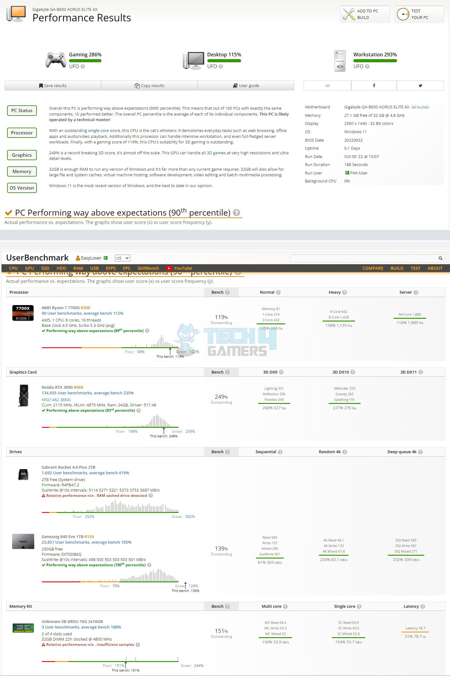 User Benchmark Scores User Benchmark Scores
Overall, we have got ourselves a workstation-grade powerful PC that is adequate enough to handle any given task. CPU Performance CineBench R23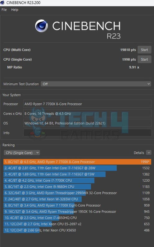 CineBench R23 Scores
Geekbench 5 CineBench R23 Scores
Geekbench 5
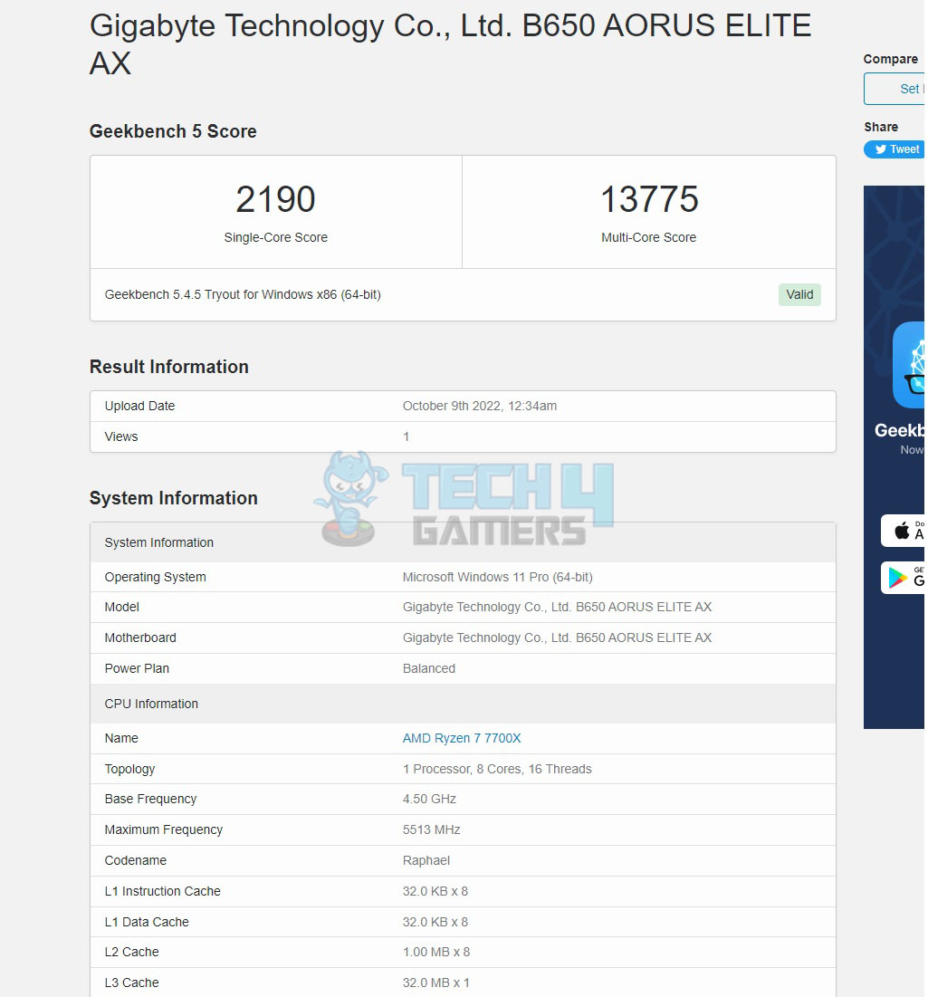 Geekbench 5
7-Zip Geekbench 5
7-Zip
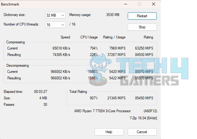 7-Zip
Hyper PI 7-Zip
Hyper PI
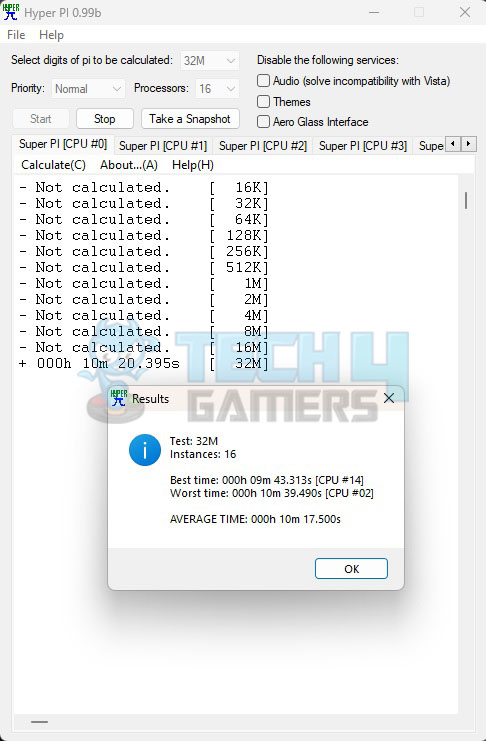 Hyper PI Hyper PI
AIDA64 Engineer 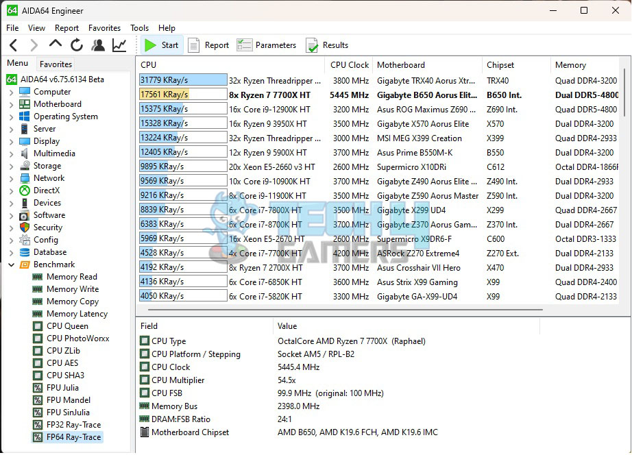 AIDA64 Engineer Scores AIDA64 Engineer Scores
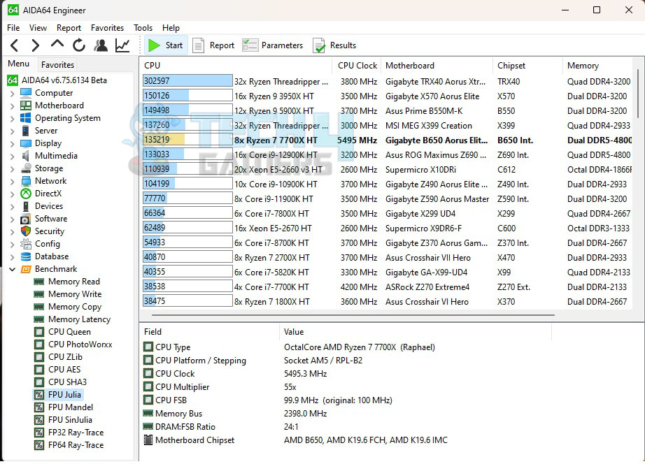 AIDA64 Engineer Scores
3DMark CPU Profile AIDA64 Engineer Scores
3DMark CPU Profile
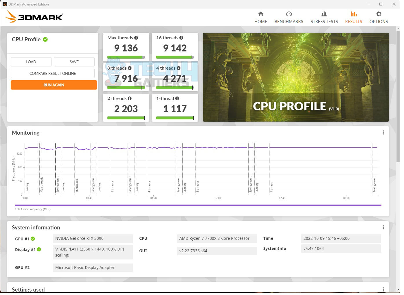 3DMark CPU Profile Scores 3DMark CPU Profile Scores
The overall CPU performance is good. Memory Performance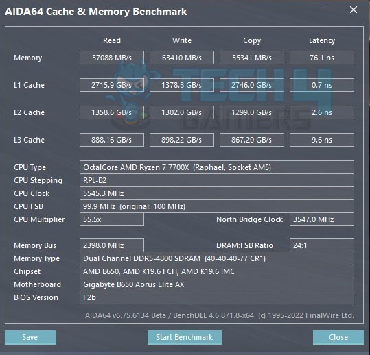 Memory Performance scores Memory Performance scores
We have got some read and write speeds but they come at the cost of high latency. 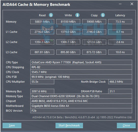 Memory Performance Scores Memory Performance Scores
We were able to push the Sabrent Rocket DDR5 kit from 4800MHz to 6200MHz and tighten the timings from 40-40-40-77 to 36-36-36-76. We have a good boost in the Write and Copy operations but the read speeds have a marginal gain. The same is the case with the Latency with a marginal improvement. This does not give any significant performance enhancement when tested in the games and the synthetic benchmarks. Next, we installed the XPG Lancer RGB 32GB kit which is rated at 6000MHz using 40-40-40-76 timing. We ran the AIDA64 memory benchmark with Low Latency Support and XMP/EXPO High Bandwidth Support disabled and then rerun the test with both settings enabled. We saw good improvement in the transfer rate as well as the latencies. Storage and USB PerformanceWe have included Sabrent Rocket Nano 2TB drive in the testing as it is a USB Type-C Gen 2 interface drive capable of 10Gbps transfer rate (theoretically). Since we have a USB Type-C Gen 2 port on the back panel, hence its testing is included. CrystalDiskMark NVMe SSD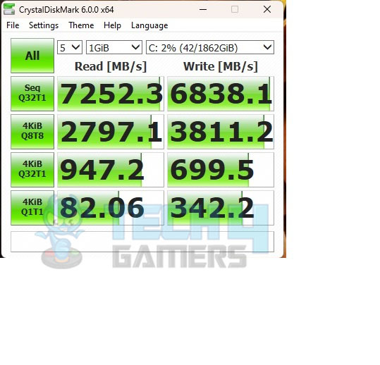 CrystalDiskMark NVMe SSD Scores
CrystalDisMark Rocket Nano 2TB CrystalDiskMark NVMe SSD Scores
CrystalDisMark Rocket Nano 2TB
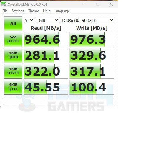 CrystalDisMark Rocket Nano 2TB Scores
ATTO NVMe SSD CrystalDisMark Rocket Nano 2TB Scores
ATTO NVMe SSD
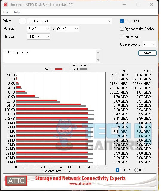 ATTO NVMe SSD
ATTO Rocket Nano 2TB ATTO NVMe SSD
ATTO Rocket Nano 2TB
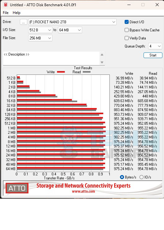 ATTO Rocket Nano 2TB Scores
3DMARK Storage NVMe SSD ATTO Rocket Nano 2TB Scores
3DMARK Storage NVMe SSD
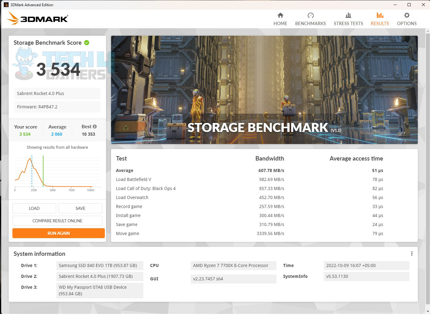 3DMARK Storage NVMe SSD Score 3DMARK Storage NVMe SSD Score
The storage performance is good as well. This motherboard is not holding anything back. Gaming Performance 3DMark FireStrikeUltra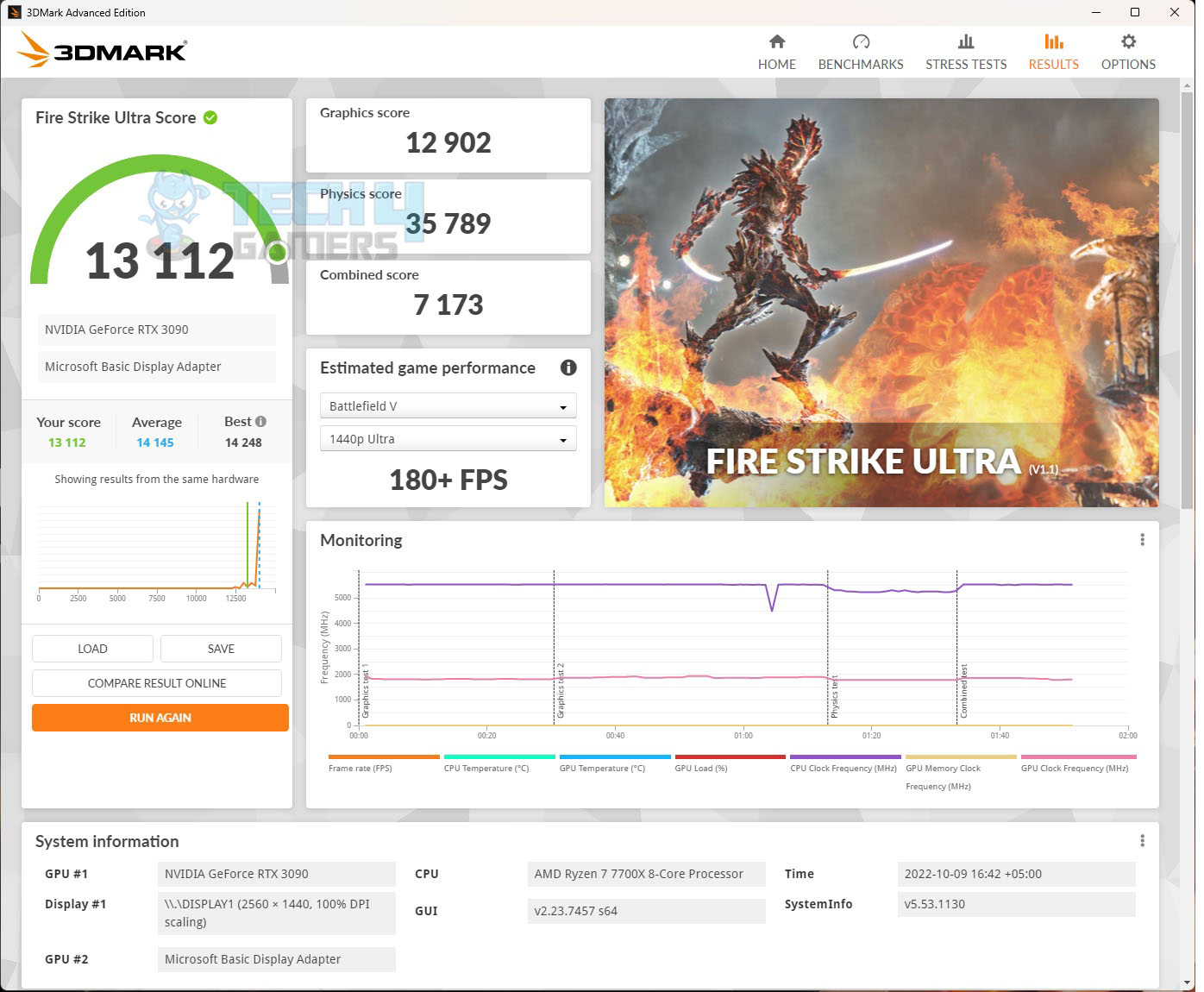 3DMark FireStrikeUltra
3DMark Time Spy Extreme 3DMark FireStrikeUltra
3DMark Time Spy Extreme
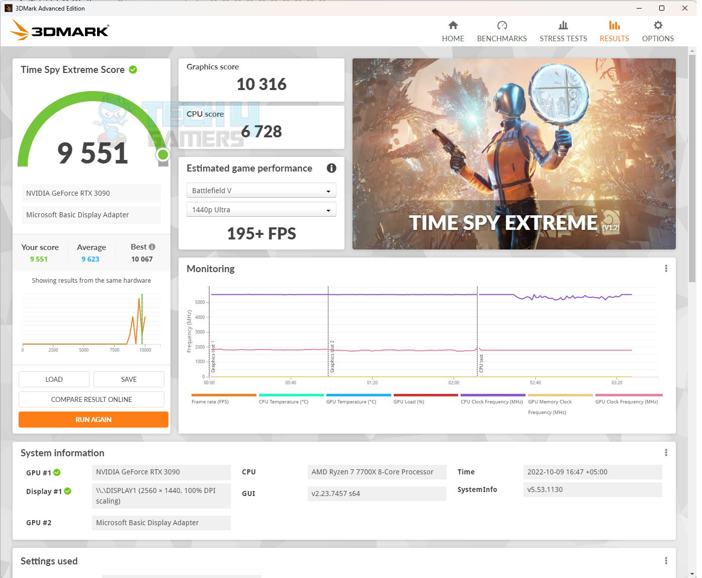 3DMark Time Spy Extreme
Red Dead Redemption 2 3DMark Time Spy Extreme
Red Dead Redemption 2
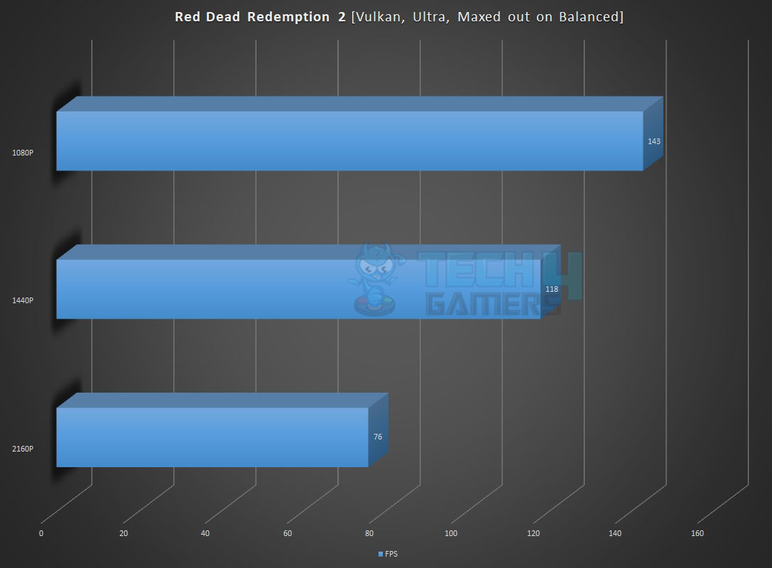 Red Dead Redemption 2
Control Red Dead Redemption 2
Control
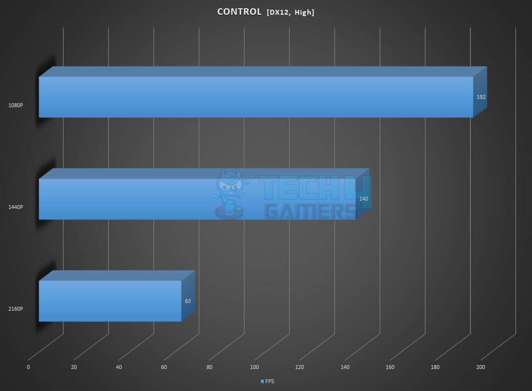 Control
DOOM Eternal Control
DOOM Eternal
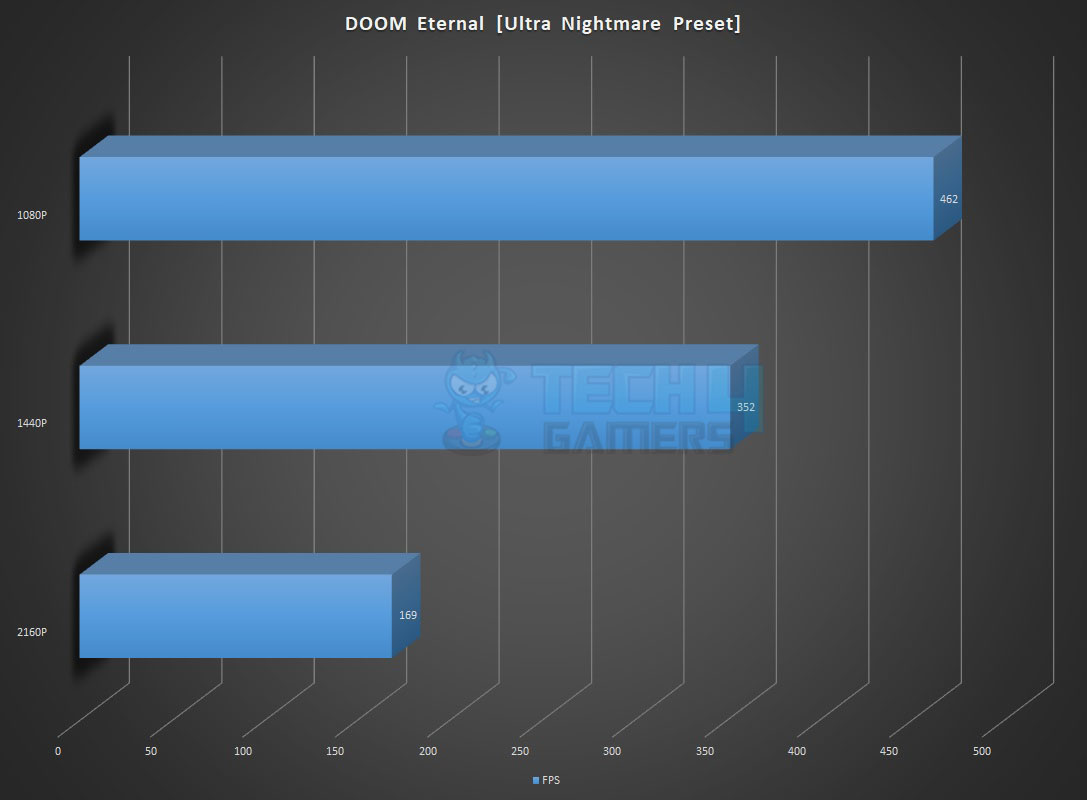 DOOM Eternal Benchmarks
Far Cry 5 DOOM Eternal Benchmarks
Far Cry 5
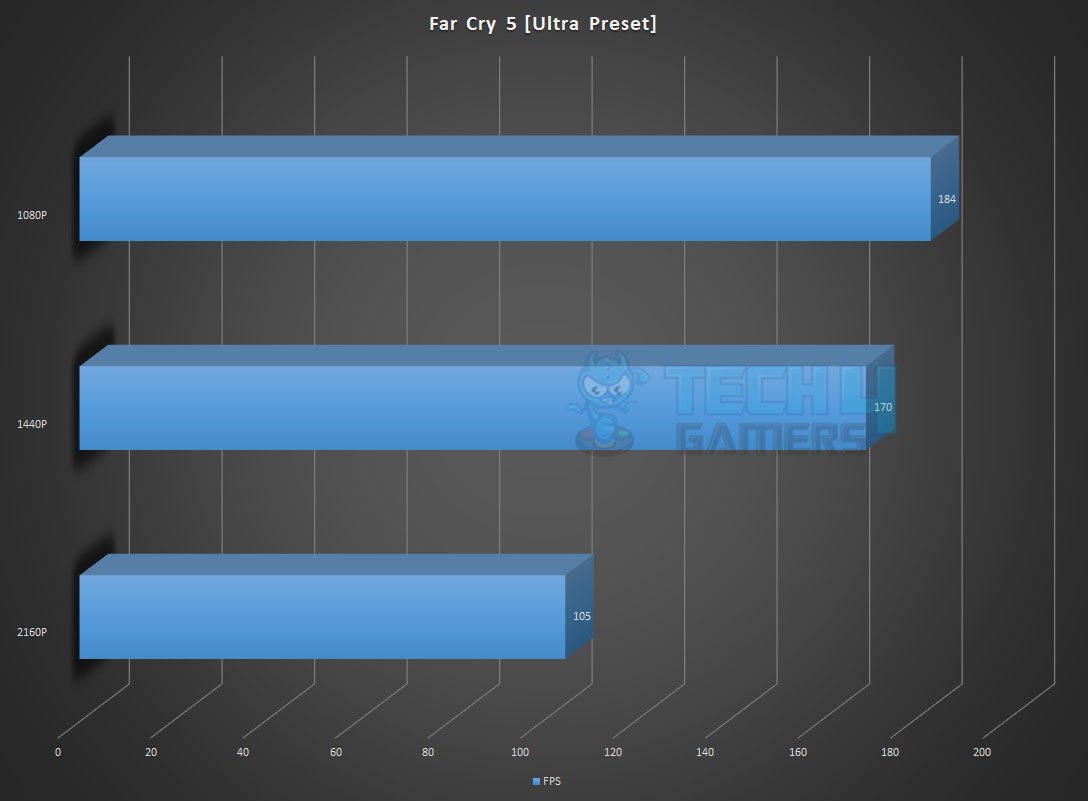 Far Cry 5 Benchmarks
Battlefield V Far Cry 5 Benchmarks
Battlefield V
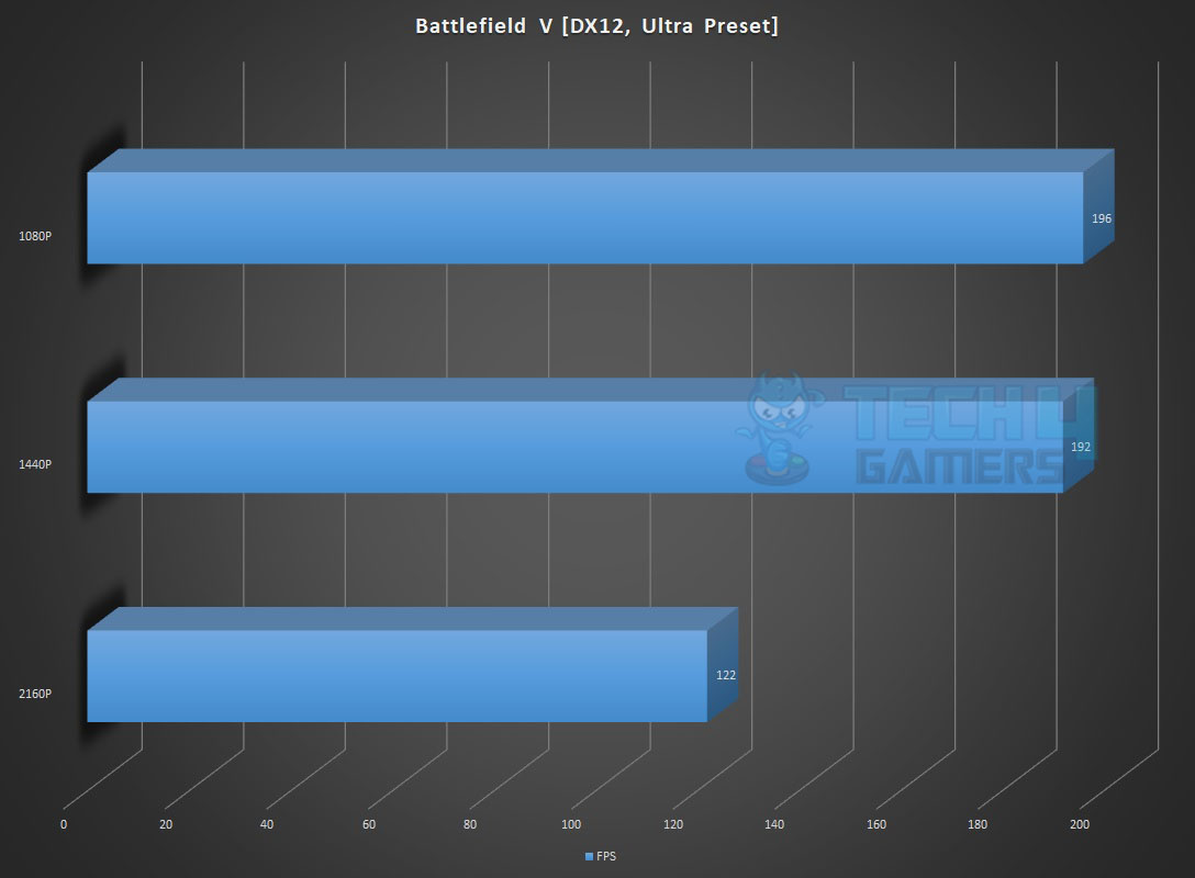 Battlefield V
Power Consumption and Thermals Battlefield V
Power Consumption and Thermals
We have left all the settings in the UEFI/BIOS on auto and stock. We only set the Fans and pump speed to run at 100% all the time. The motherboard picked the Memory timing and frequency correctly since the Sabrent Rocket DDR5 kits are running at JEDEC default. The power mode was Balanced in the Windows. The system was left idle for 30 minutes with HWInfo64 running in the background recording the values. CPU RAM NVMe SSD Graphics Card Idle Temp 45°C 33.8°C 33°C 40.6°C Idle Power Draw 12.448W [Package] 0.125W N/A 82.551 (Rail)
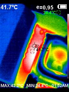
The frequencies on the cores were in the range of 3000MHz+ Next, the Cinebench R23 System Stability test was run for 30 minutes to record the thermals, power, and frequency behavior. The temperature of the CPU was 95.4°C with a VCore value of 1.404V. The frequencies were in the range of 5000MHz. The package power draw was 123.187W. The graphics card under gaming load was drawing near 395W power with a maximum temperature of 75° We used a custom fan curve for the graphics card so the fans were running at high speed. The Sabrent Rocket 4 Plus NVMe SSD was doing 60°C under load.The SilverStone Air Penetrator 120SK A-RGB was blowing focused air toward the graphics card and NVMe ports at its full speed. Thermal ImagingWe have used the Hti HT18 Thermal camera to record the thermals of the VRM area of the motherboard under load using Cinebench R23.
The MOSFETs were operating at around 42.2°C at an ambient of 31°C. The onboard sensor reported 41°C. So, we can say that the error margin is reduced and the temperature is near accurate though we did not use the external temperature sensor on the back of the motherboard. The SilverStone Air Penetrator 120SK A-RGB was blowing focused air at its full speed towards the CPU socket area. ConclusionGIGABYTE B650 AORUS ELITE AX is the third-highest motherboard in the B650 lineup. Don’t expect the price to be that low on this mid-range, budget-segment motherboard. This motherboard is powered by an AMD B650 chipset coupled with the AM5 socket. It has adequate features though some hit-and-miss design elements are observed. GIGABYTE has focused on durability and high-performance in this motherboard. The motherboard features an AM5 socket compatible with AMD 7000 series CPUs and DDR5 slots. The DIMM slots are not SMD reinforced as we have seen in the X670E AORUS MASTER and but they are implemented on another PCB layer with multiple shielding to ensure maximum and stable performance. We have a total of 3x PCIe slots. There is no Gen PCIe slot on this motherboard instead we have a Gen 5-based M.2 NVMe SSD port wired to the CPU. The top PCIe slot is Gen 4 x16 and wired to the CPU. The other two PCIe slots are wired to the chipset on the Gen 3 bus and both are rated at X1 speed (my complaint here). At least one should have been X4! The very reason is the chipset implementation. Both slots shared the bus with the M.2 Wi-Fi 6E module, and 2.5GbE LAN. When it comes to the M.2 ports, this motherboard features 1x M.2 NVMe Gen 5 port at x4 speed whereas there are two more ports. One of them is wired to the CPU socket and it is Gen 4 port at X4 speed. The last port is connected to the chipset and is still Gen 4 X4. There are tons of USB ports and hubs on this motherboard including the 1x USB 3.2 Gen 2×2 Type-C port (on the mid-board for the front panel) and 1x USB Type-C Gen port on the Rear I/O. GIGABYTE has provided Wi-Fi 6E and Bluetooth 5.3 wireless connectivity in addition to the Intel 2.5GbE LAN port. The WiFi module is from MediaTek and the 2.5GbE LAN is from RealTek. Not sure why but one clue would be expensive Intel equivalent chips. However, GIGABYTE has mentioned that the Rev 1.1 of this motherboard will have Intel chips for wireless and wired connectivity. For troubleshooting, there are LED indicators. There is a button that is programmable from the UEFI/BIOS. GIGABYTE has employed TMOS-based massive heatsinks for effective cooling of the VRM/MOSFETs. It is a one-piece design and a larger surface improves the cooling performance. TMOS features several channels and inlets on the heatsink. This design allows for the airflow to go through which leads to a great improvement in the heat transfer performance. Both heatsinks are connected with a 6mm nickel-plated copper heat pipe. The thermal pads are rated at 7 W/mK. The Thermal Guard helps to keep the temperature of M.2 SSDs in check. GIGABYTE has provided single-sided thermal pads for the SSDs. There is an EZ-Latch on the top PCIe slot which is actually an extender of the locker and it makes it easier to access the locker in a space-constrained area and makes a low-profile locker latch to a high profile. The M.2 SSD ports have EZ-Latch which is a tool-free mechanism to install the SSDs. The Audio solution is ordinary as it is driven by RealTek ALC897. SuperIO chip is from iTE 8689E. There are 6 fans/pump headers each rated for 24W using 2A. These are powered and controlled by nuvoton 3947S. There are 5 onboard thermal sensors. There is no external sensor. The CPU power delivery includes twin digital 14 phases governed by Infineon XDPE192C3B PWM controller with Infineon TDA21472 SPS 70A MOSFET. These are for the VCore. There are 2x ON NCP303160 SPS 60A MOSFET for SOC (iGPU) and 1x Renesas ISL99390 SPS 30A MOSFET for MISC (PCIe Lanes). One should take full advantage of the XMP/EXPO High Bandwidth and Low Latency Support settings. Enable both settings in the UEFI/BIOS and you will see improvement in the overall transfer rates and more importantly the latency. We saw latency dropping from 73.5 to 61.7ns and the read/write/copy speeds were improved as well. The latest BIOS f2b was used for the testing. For some reason, we saw and downloaded the f2c BIOS from their site but later on it was removed. The overall performance of the motherboard is quite good as it has chewed whatever we have thrown at it. The B650 would be the main-stream selling boards based on the balanced feature set and pricing since the high-end boards particularly in the X670E/X670 are quite high priced-tag. The MOSFET cooling is quite good. The storage and the gaming performance is good as well. The network connectivity is fine as well. The audio solution is just ok but still covers the majority of the need. GIGABYTE is offering 1+2 warranty on this motherboard.
Thank you! Please share your positive feedback. 🔋 How could we improve this post? Please Help us. 😔  Nauman Siddique Nauman Siddique[Hardware Reviewer & Editor] Meet Nauman Siddique, a highly experienced computer science graduate with more than 15 years of knowledge in technology. Nauman is an expert in the field known for his deep understanding of computer hardware. As a tech tester, insightful reviewer, and skilled hardware editor, Nauman carefully breaks down important parts like motherboards, graphics cards, processors, PC cases, CPU coolers, and more. 15+ years of PC Building Experience 10+ years of first-hand knowledge of technology 7+ years of doing in-depth testing of PC Hardware A motivated individual with a keen interest in tech testing from multiple angles. I majored in Computer Science with a Masters in Marketing Previously worked at eXputer, EnosTech, and Appuals.Get In Touch: [email protected] |

【本文地址】